ProScan motorised XY microscope stages
- Technology
- Photonics accessories
- Partner
- Prior Scientific
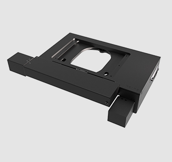
ProScan motorised XY microscope stages support automated scanning, image acquisition and repeatable sample positioning. The range includes configurations for upright and inverted microscopes, plus larger stages for industrial inspection and wafer imaging. Model-dependent travel areas accommodate individual slides, multiwell plates, multiple-slide holders and semiconductor wafers up to 12 in. Precision stepper-motor stages use ground recirculating ball screws, while linear-motor technology is available for applications requiring higher acceleration and speed. Selected configurations can incorporate linear encoders for closed-loop positioning and improved long-range repeatability.
Intelligent Scanning Technology stores correction data for each stage to support consistent movement across its working area. Larger stages use full mapping to improve metric accuracy over extended travel ranges. Adjustable internal limits help protect microscope components, while interchangeable holders support a wide variety of specimen formats. Integration with the ProScan III controller enables coordinated operation with motorised focus systems, filter wheels, shutters and other imaging components.
Range features
A high level overview of what this range offers
- Multiple stage formats: Support upright, inverted and reflected-light microscope arrangements.
- Model-dependent XY travel: Accommodates samples ranging from individual slides to semiconductor wafers up to 12 in.
- Precision stepper-motor configurations: Allow movement speed and positioning resolution to be balanced for the application.
- Linear-motor options: Provide higher acceleration and stage speeds for applications requiring shorter movement cycles.
- Ground recirculating ball screws: Deliver smooth movement with mechanically controlled backlash.
- Optional linear encoders: Enable closed-loop position feedback on compatible stage configurations.
- Intelligent Scanning Technology: Applies stored correction data to requested movements across the stage.
- Full mapping on larger stages: Supports metric accuracy across extended travel areas used for wafer and large-sample imaging.
- Adjustable internal travel limits: Help reduce the risk of collisions with microscope components and accessories.
- Interchangeable specimen holders: Support slides, well plates, Petri dishes, flasks, metallurgical samples and wafers.
- USB and RS232 control: Simplifies connection to computers and compatible imaging software through the ProScan III controller.
- Programmable motion settings: Allow speed, acceleration and drive current to be adapted to the installed configuration.
What’s in this range?
All the variants in the range and a comparison of what they offer
Product range specifications
| Specification | Details |
|---|---|
Product type | Motorised XY microscope stage range |
Positioning axes | X and Y |
Microscope formats | Upright, inverted and reflected-light configurations |
Motor technologies | Precision stepper motors; linear-motor options available |
Selected XY travel areas | 108 × 108 mm, 114 × 76 mm, 154 × 154 mm, 240 × 76 mm, 255 × 215 mm and 302 × 302 mm |
Maximum stage speed | Up to 300 mm/s, configuration-dependent |
Minimum XY step size | From 0.01 µm |
Typical repeatability | Less than 1 µm |
Linear scale options | 0.1 µm or 0.05 µm |
Ball-screw pitches | 1 mm, 2 mm, 4 mm or 5 mm, depending on stage configuration |
Ball-screw construction | Ground recirculating ball screws with preloaded nuts |
Limit switches | Adjustable in X and Y |
Stage construction | Precision-machined cast aluminium plates |
Position correction | Intelligent Scanning Technology or full mapping, depending on model |
Supported specimen types | Slides, microtitre plates, Petri dishes, flasks, metallurgical samples and semiconductor wafers |
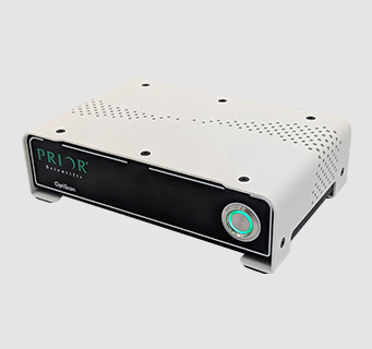
Control platform | ProScan III microscope automation controller |
Computer interfaces | USB virtual COM and RS232C |
Serial communication rates | 9,600, 19,200, 38,400 and 115,200 baud |
Selected stage family comparison
| Specification | H101A | H101F | H117 | H138A | H105 | H116 | H112 | HT1111LC |
|---|---|---|---|---|---|---|---|---|
Stage format | Upright | Upright, flat top | Inverted | Upright, extended X travel | Upright, large format | Upright, large format | Upright, large format | Solid-frame reflected-light stage |
Nominal XY travel | 114 × 76 mm | 114 × 76 mm class | 114 × 76 mm | 240 × 76 mm | 154 × 154 mm | 255 × 215 mm | 302 × 302 mm | 108 × 108 mm |
Typical sample format | Well plates and general microscopy samples | Samples requiring increased objective clearance | Well plates and live-cell imaging formats | Up to eight slides | Wafers up to 6 in | Wafers up to 8 in | Wafers up to 12 in | Metallurgical samples and hardness testing |
Ball-screw configuration | 1 mm or 2 mm | 1 mm or 2 mm | 1 mm or 2 mm | 2 mm | 2 mm | 2 mm | 2 mm | Stage-specific configuration |
Motor configuration | 400-step or 200-step | 400-step or 200-step | 400-step or 200-step | 200-step | Configuration-dependent | Configuration-dependent | Configuration-dependent | Configuration-dependent |
Position correction | Intelligent Scanning Technology | Intelligent Scanning Technology | Intelligent Scanning Technology | Intelligent Scanning Technology | Full mapping | Full mapping | Full mapping | Intelligent Scanning Technology |
Encoder availability | Optional | Optional | Optional | 0.1 µm option | Optional | Optional | Optional | Configuration-dependent |
FAQs
for ProScan motorised XY microscope stages
Select the travel range by considering the complete imaging area, sample holder and clearance required around the specimen. H101A and H117 configurations provide approximately 114 × 76 mm of travel for well plates and general microscopy samples, while the H138A extends X travel to 240 mm for multiple-slide scanning. Larger H105, H116 and H112 stages provide 154 × 154 mm, 255 × 215 mm and 302 × 302 mm respectively for wafer and large-format inspection. The moving envelope may be larger than the nominal travel area, so the microscope frame, objectives, condenser and surrounding equipment should be checked throughout the full XY movement before selecting a stage.
The 1 mm ball-screw configuration prioritises positioning resolution, while the 2 mm version supports faster movement for the same number of motor revolutions. Selected H101A and H117 stages combine a 1 mm screw with a 400-step motor for accuracy-focused applications, or a 2 mm screw with a 200-step motor where scanning speed is more important. The appropriate choice depends on objective magnification, pixel size, tile overlap and the distance travelled between acquisition points. A finer mechanical configuration does not automatically shorten settling time, so the complete acquisition cycle should be assessed rather than comparing only nominal maximum velocity.
An encoded stage is preferable when the application requires closed-loop verification of the actual XY position. Linear scale options of 0.1 µm or 0.05 µm are available for compatible configurations, while the overall range has a typical repeatability figure below 1 µm. Encoder feedback is particularly relevant to multiposition time-lapse imaging, metrology and workflows that repeatedly approach coordinates from different directions. A non-encoded stage may be sufficient for routine scanning when movement follows a controlled path and individual stage correction data are applied. Mounting rigidity, sample mass and thermal conditions should still be considered because they can influence complete-system performance.
Intelligent Scanning Technology uses correction data measured for the individual stage and stored with that stage. The controller applies this information when calculating requested movements, supporting metric accuracy and repeatable tile placement. Full mapping uses a denser set of measurements across the travel area and is applied to larger stages such as the H105, H116 and H112 families. This is useful where small positioning errors could accumulate across a large wafer or stitched image. The correction system supports stage performance, but application-level calibration may still be required to account for the camera, optics, sample mounting and image-processing workflow.
The selected stage must match the microscope format, substage interface and available clearance around the optical path. Upright and inverted stages use different mechanical arrangements, while the H101F flat-top design places the sample close to the upper stage surface to increase objective and nosepiece clearance. The full moving footprint should be checked against the microscope frame, condenser, objectives, cables and any incubation or probing equipment. A suitable holder is also required for the intended slides, dishes, plates or wafers. Adjustable XY limits can then restrict movement where the microscope or installed accessories reduce the usable travel envelope.
The stages are operated through the ProScan III microscope automation controller, which provides USB virtual COM and RS232C interfaces. Serial communication can be configured at 9,600, 19,200, 38,400 or 115,200 baud, allowing integration with laboratory software and OEM control applications. A software development kit and ASCII command access support custom integration where a standard imaging package is not used. The controller can coordinate the XY stage with focus drives, filter wheels, shutters and additional motorised axes. Speed, acceleration and drive current can also be programmed to suit the stage mechanics, sample mass and required movement profile.
Maximum velocity is only one part of the imaging cycle and should not be used as the sole throughput measure. The range supports stage speeds up to 300 mm/s in suitable configurations, while ball-screw pitch, motor type, acceleration settings and sample mass affect the speed achievable in practice. Short movements may be dominated by acceleration, deceleration and settling rather than top velocity. A 2 mm ball-screw configuration can support faster scanning than a 1 mm configuration, whereas linear-motor stages are intended for applications requiring higher acceleration. Throughput estimates should include movement distance, settling criteria, exposure time, autofocus operation and any filter or illumination changes.