Capacitive high- voltage dividers
- Technology
- Photonics accessories
- Partner
- Pearson Electronics
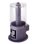
These high-voltage capacitive voltage dividers are designed for measurement set-ups where the original signal exceeds the direct input range of conventional instrumentation. Each model uses two capacitors connected in series, with a guarded pick-up ring producing a lower proportional output voltage. The range provides different combinations of maximum pulse voltage, division ratio, frequency response, rise time and added circuit capacitance. Oil-calibrated models are intended primarily for installation in high-voltage insulating oil, while a dedicated air-calibrated VD-305A variant is available for operation without an oil dielectric.
The stated frequency ranges and droop rates are based on connection to a 1 MΩ measuring load. These characteristics support high-voltage test benches, pulsed-power research and component evaluation where the selected model’s electrical ratings match the test conditions. Model selection should account for the operating medium, pulse duration, expected waveform, measurement input impedance and permitted circuit loading.
Range features
A high level overview of what this range offers
- Coaxial capacitive divider architecture – Produces a proportional low-voltage signal for measuring high-potential waveforms.
- Maximum pulse voltage up to 500 kV in oil – Supports high-voltage pulse measurement within an insulating-oil environment.
- Air ratings up to 90 kV – Provides options for test arrangements that do not use insulating oil.
- 5,000:1 and 10,000:1 division ratios – Allows output scaling to be matched to the measuring instrument.
- Frequency coverage up to 4 MHz – Supports waveform measurement across the model-dependent operating range.
- Usable rise times from 100 to 200 ns – Allows engineers to select a divider around the required pulse-edge response.
- Approximately 8 to 38 pF added capacitance – Provides defined values for assessing measurement-circuit loading.
- Unit-specific measured ratio marked on the nameplate – Enables calculations to use the individual divider’s calibrated ratio.
- Division-ratio temperature compensation of ±1% from 20 to 80 °C – Limits ratio variation across the stated temperature range.
- Custom division ratios and air calibration available – Accommodates measurement arrangements outside the standard configurations.
- Isolated output connector shell – Allows the earth connection point to be selected to help control ground loops.
Downloads
for Capacitive high- voltage dividers
What’s in this range?
All the variants in the range and a comparison of what they offer
General specifications
| Specification | Value |
|---|---|
Nominal division ratios | 5,000:1 or 10,000:1, depending on model and calibration |
Maximum pulse voltage across range | Up to 500 kV in oil and 90 kV in air |
Frequency coverage across range | 15 Hz to 4 MHz, depending on model and operating medium |
Frequency and droop load basis | 1 MΩ measuring load |
Droop rate across range | 0.01 to 0.05%/µs |
Usable rise time across range | 100 to 200 ns |
Capacitance added to measured circuit | Approximately 8 to 38 pF |
Division-ratio accuracy | ±5% at the specified calibration temperature |
Oil calibration temperature | 35 °C |
Air calibration temperature | 22 °C for the air-calibrated VD-305A |
Division-ratio temperature compensation | ±1% from 20 to 80 °C |
Standard oil dielectric | High-voltage insulating oil with an approximate dielectric constant of 2.3 |
Pulse-rating duration basis | Up to 5 µs; voltage derating is required for longer pulses |
Output network | Pick-up ring connected to the output centre conductor through a 50 Ω resistor |
Model comparison
| Specification | VD-301 | VD-305A | VD-305A-10,000 | VD-305A-AIR | VD-500A |
|---|---|---|---|---|---|
Maximum pulse voltage in oil | 400 kV | 300 kV | 300 kV | — | 500 kV |
Maximum pulse voltage in air | 75 kV | 50 kV | 50 kV | 50 kV | 90 kV |
Voltage division ratio | 5,000:1 in oil | 5,000:1 nominal in oil | 10,000:1 in oil | 5,000:1 in air | 10,000:1 in oil |
Frequency range into 1 MΩ | 25 Hz to 3 MHz | 30 Hz to 4 MHz | 30 Hz to 4 MHz | 70 Hz to 4 MHz | 15 Hz to 2 MHz |
Droop rate into 1 MΩ | 0.015%/µs | 0.02%/µs | 0.02%/µs | 0.05%/µs | 0.01%/µs |
Usable rise time | 150 ns | 100 ns | 100 ns | 100 ns | 200 ns |
Approximate added capacitance | 28 pF | 18 pF | 18 pF | 8 pF | 38 pF |
FAQs
for Capacitive high- voltage dividers
Choose the operating dielectric first because the calibrated division ratio and maximum pulse voltage depend on whether the divider is used in oil or air. The oil-calibrated models cover maximum pulse voltages from 300 to 500 kV, while their stated air limits range from 50 to 90 kV. The dedicated VD-305A-AIR is calibrated at 5,000:1 in air and is rated to 50 kV, with approximately 8 pF added capacitance. An oil-calibrated 5,000:1 unit can shift to about 11,500:1 in air, while the VD-500A can shift to approximately 23,000:1. Specify the intended dielectric environment when selecting the model rather than applying an oil calibration factor to an air installation.
The division ratio determines the approximate voltage delivered to the measuring instrument, so it must be considered alongside the instrument’s maximum input rating. At 5,000:1, an input of 300 kV produces a nominal 60 V output, while 50 kV produces approximately 10 V. At 10,000:1, 300 kV produces about 30 V and 500 kV produces about 50 V. These calculations use nominal ratios; the exact measured ratio marked on the individual divider should be used for final waveform scaling. Any external attenuation, cable effects and measuring-instrument limits must also be included when defining the complete acquisition chain.
Not without separately evaluating and calibrating the resulting measurement network. The quoted frequency ranges and droop rates are specified with a 1 MΩ load, so changing the input to 50 Ω can alter the division behaviour and invalidate the listed response figures. The internal 50 Ω resistor between the pick-up ring and output centre conductor does not by itself make the divider a conventional 50 Ω matched source. Additional cable, termination and instrument loading can also affect the observed waveform. For measurements that require 50 Ω termination, model the complete network and confirm its ratio, bandwidth and pulse response under the intended connection conditions.
Use the frequency range to assess the required spectral coverage and the rise-time figure to judge how closely the divider can follow a fast pulse edge. The VD-305A variants extend to 4 MHz and provide a usable rise time of 100 ns, while the VD-301 reaches 3 MHz with a 150 ns rise time. The higher-voltage VD-500A extends to 2 MHz and has a 200 ns usable rise time. Low-frequency limits and droop also matter when measuring wider pulses or signals with longer flat-top periods. Select a model with electrical headroom beyond the expected waveform content and verify the response of the divider, cable and measuring instrument as one system.
The nominal division ratio is stated as accurate to ±5% at the relevant calibration temperature, which is 35 °C for oil calibration and 22 °C for the air-calibrated VD-305A. Each unit carries its exact measured division ratio on the nameplate, and that value should be used instead of relying solely on the nominal 5,000:1 or 10,000:1 figure. The ratio is temperature compensated to ±1% over the range from 20 to 80 °C. This compensation describes divider-ratio variation rather than total measurement-system uncertainty. For tighter uncertainty requirements, calibrate the complete chain, including the divider, output cable, any external attenuation and the acquisition instrument.
No; the stated maximum pulse voltage ratings are based on pulse durations up to 5 µs. Longer pulses increase electrical stress duration, so the listed oil and air voltage limits should not be applied automatically outside that condition. A universal derating curve is not defined for the range, meaning longer pulse widths require an application-specific voltage review. Repetitive operation, duty cycle, dielectric condition and the surrounding high-voltage geometry may also need to be considered when establishing a suitable operating level. Treat the published rating as a short-pulse boundary and obtain an agreed derated voltage before using longer pulses.
The output connector shell must be connected to earth even though it is electrically isolated from the case when supplied. This isolation allows the installation designer to choose the location and arrangement of the earth connection, which can help control ground loops in the measuring system. The high-voltage conductor should have a smooth surface, adequate diameter and no sharp points or edges that could promote corona or arcing. The outer conductor of standard RG-58 coaxial cable can provide a practical smooth conductor for this connection. Keep the conductor as far as practicable from the acrylic chimney, divider case, output cable and other earthed structures.
The added capacitance ranges from approximately 8 pF for the air-calibrated VD-305A to 38 pF for the VD-500A. The standard and 10,000:1 VD-305A variants add about 18 pF, while the VD-301 adds approximately 28 pF. This capacitance can draw additional current during rapid voltage transitions and may influence a high-impedance or low-energy pulse source. The lowest-capacitance model is therefore not automatically the correct choice because voltage rating, calibration medium, division ratio and bandwidth must also match the application. Include the stated capacitance in the transient model of the test circuit and check that it does not materially alter the waveform being measured.