PS300 High Voltage Power Supplies
- Technology
- Scientific instruments
- Partner
- Stanford Research Systems (SRS)
The PS300 Series covers seven programmable DC high voltage bench power supplies for laboratory and automated test applications. Three 25 W models provide selectable positive or negative outputs from ±1.25 kV to ±5 kV, while four 10 W models provide fixed positive or negative outputs at 10 kV or 20 kV. Programmable voltage limits, current limits and current trips help protect the connected load and establish controlled operating boundaries. Separate LED displays show measured output voltage and current, supported by indicators for limits, trips, operating state and high voltage enable.
Computer control is available through GPIB, with RS-232 additionally fitted as standard to the 10 W models. A 0 to 10 V DC input enables external analogue programming, while voltage and current monitor outputs support data acquisition and system integration. Up to nine configurations can be stored for repeatable test procedures. The compact half-rack bench housing can also be installed in 19-inch rack systems using the appropriate mounting accessories.
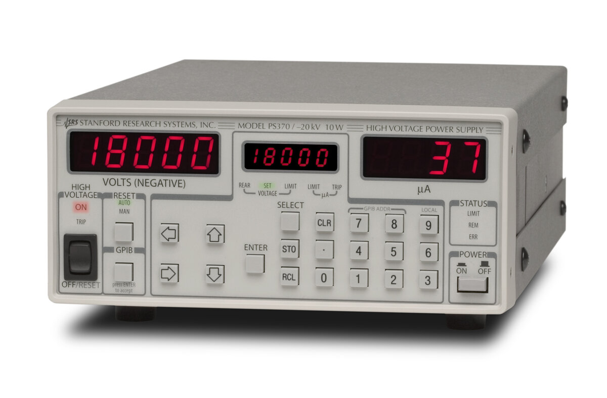
Range features
A high level overview of what this range offers
- Seven voltage and current configurations: Select the required polarity, maximum output voltage and load current.
- Dual-polarity 25 W models: Choose positive or negative high voltage for different test procedures.
- Single-polarity outputs up to 20 kV: Address higher-voltage applications requiring positive or negative DC output.
- 1 V set and display resolution: Make repeatable digital adjustments throughout the available output range.
- Programmable voltage and current limits: Protect the connected load and establish controlled operating boundaries.
- Programmable current trip: Disable the high voltage when the selected current threshold is exceeded.
- Arc and short-circuit protection: Support loads that may experience breakdown or transient faults.
- Two LED measurement displays: Monitor delivered voltage and current simultaneously.
- Nine stored configurations: Reduce setup time when repeating established test routines.
- Digital and analogue control: Support manual operation, computer-controlled testing and external 0 to 10 V programming.
- Voltage and current monitor outputs: Connect measurement logging or external control equipment.
- Rack-mounting options: Integrate the half-rack instruments into 19-inch test systems.
Downloads
for PS300 High Voltage Power Supplies
What’s in this range?
All the variants in the range and a comparison of what they offer
Specifications
| Specification | PS310, PS325 and PS350 | PS355, PS365, PS370 and PS375 |
|---|---|---|
Output configuration | Dual polarity, 25 W | Single polarity, 10 W |
Voltage set accuracy | 0.01% + 0.05% of full scale | 0.06% of full scale |
Voltage display accuracy | Set accuracy ±1 V typical; ±2 V maximum | Set accuracy ±1 V typical; ±2 V maximum |
Voltage resolution | 1 V, set and display | 1 V, set and display |
Voltage resettability | 1 V | 1 V |
Voltage limit range | 0 to 100% of full scale | 0 to 100% of full scale |
Line regulation | 0.001% for ±10% line change | 0.001% for ±10% line change |
Load regulation | 0.005% for 100% load change | 0.04% for 100% load change |
Output ripple, RMS | Less than 0.002% of full scale | Less than 0.01% of full scale, 300 Hz to 300 kHz |
Current limit range | 0 to 105% of full scale | 0 to 105% of full scale |
Current trip range | 10 µA to 105% of full scale, excluding stored output charge | 10 µA to 105% of full scale, excluding stored output charge |
Trip response time | Less than 10 µs | Less than 10 ms |
Maximum stored output charge | Not specified | Less than 20 µC for PS355 and PS365; less than 40 µC for PS370 and PS375 |
Current set accuracy | 0.01% + 0.05% of full scale | 0.5% of full scale |
Current resolution | ±10 µA for PS310 and PS325; ±1 µA for PS350 | ±1 µA |
Current display accuracy | ±10 µA typical and ±20 µA maximum for PS310 and PS325; ±1 µA typical and ±2 µA maximum for PS350 | ±1 µA typical; ±2 µA maximum |
Stability | 0.01% per hour; less than 0.03% per 8 hours | Not specified |
Temperature drift | 50 ppm/°C from 10°C to 40°C, typical | 50 ppm/°C from 10°C to 40°C, typical |
Recovery time | 12 ms for a 40% load-current step, typical | 12 ms for a 40% load-current step, typical |
Discharge time | Less than 6 seconds to below 1% of full-scale voltage with no load, typical | Less than 6 seconds to below 1% of full-scale voltage with no load, typical |
Analogue monitor scale | 0 to +10 V for zero to full-scale output, independent of polarity | 0 to +10 V for zero to full-scale output, independent of polarity |
Monitor output current | 10 mA maximum | 10 mA maximum |
Monitor output impedance | Less than 1 Ω | Less than 100 Ω |
Monitor output accuracy | ±0.2% of full scale | ±0.2% of full scale |
Monitor update rate | 8 Hz | 87.5 Hz |
External voltage-set input | 0 to +10 V for zero to full-scale output, independent of polarity | 0 to +10 V for zero to full-scale output, independent of polarity |
External input impedance | 1 MΩ | 1 MΩ |
External set accuracy | ±0.2% of full scale | ±0.2% of full scale |
External set update rate | 16 Hz | 87.5 Hz |
Output slew rate | Less than 0.3 seconds from zero to full scale at full load | 7,000 V/s typical for PS355 and PS365; 14,000 V/s typical for PS370 and PS375 |
GPIB interface | Optional | Standard |
RS-232 interface | Not fitted | Standard; DCE, 9600 baud, no parity, 8 data bits and 1 stop bit |
High voltage connector | Kings Type 1704-1 | Kings Type 1064-1 for PS355 and PS365; Kings Type 1764-1 for PS370 and PS375 |
Mating connector | Kings Type 1705-1 | Kings Type 1065-1 for PS355 and PS365; Kings Type 1765-1 for PS370 and PS375 |
Dimensions, W × H × L | 8.1″ × 3.5″ × 16.0″ | 8.1″ × 3.5″ × 14.0″ |
Weight | 8 lb | 8 lb |
AC power | 50 W; 100, 120, 220 or 240 V AC; 50 or 60 Hz | 75 W; 100 to 240 V AC; 50 to 60 Hz |
Ground reference | High voltage output and BNC shields connected to chassis ground; output cannot be floated | High voltage output and BNC shields connected to chassis ground; output cannot be floated |
Warm-up requirement | One hour before rated performance applies | One hour before rated performance applies |
Warranty | One year covering parts and labour for material and workmanship defects | One year covering parts and labour for material and workmanship defects |
Variant Comparison
| Specification | PS310 | PS325 | PS350 | PS355 | PS365 | PS370 | PS375 |
|---|---|---|---|---|---|---|---|
Output voltage range | ±12 V to ±1.25 kV | ±25 V to ±2.5 kV | ±100 V to ±5 kV | −100 V to −10 kV | +100 V to +10 kV | −100 V to −20 kV | +100 V to +20 kV |
Maximum current | 20 mA | 10 mA | 5 mA | 1 mA | 1 mA | 0.5 mA | 0.5 mA |
Output configuration | Dual polarity | Dual polarity | Dual polarity | Negative only | Positive only | Negative only | Positive only |
Power class | 25 W | 25 W | 25 W | 10 W | 10 W | 10 W | 10 W |
FAQs
for PS300 High Voltage Power Supplies
Select the model by considering the required polarity, maximum voltage and load current together. The PS310, PS325 and PS350 provide dual-polarity ranges of ±1.25 kV at 20 mA, ±2.5 kV at 10 mA and ±5 kV at 5 mA respectively, while the other models provide fixed positive or negative outputs at 10 kV or 20 kV. The dual-polarity instruments use a polarity selector and must be powered down before the polarity is changed. They should therefore be used where either polarity is needed between test runs, rather than for rapid electronic polarity reversal. Allow current headroom for the load and connected high voltage cable when making the final selection.
Yes, the programmable current limit allows the supply to regulate by reducing its output voltage when the load attempts to draw more than the selected current. The current limit can be set from zero to 105% of full scale, while the separate current-trip threshold extends from 10 µA to 105% of full scale. A current trip disables the high voltage instead of maintaining current-limited operation, with response times below 10 µs for the 25 W models and below 10 ms for the 10 W models. Manual and automatic reset modes determine how the instrument responds after a trip. Use current limiting for controlled constant-current operation and the trip function when the test requires a complete shutdown after an overload.
Automation can be implemented through either a digital interface or the rear-panel analogue connections. GPIB is optional on the PS310, PS325 and PS350, while the PS355, PS365, PS370 and PS375 include both GPIB and RS-232 as standard. The RS-232 port operates as DCE at 9600 baud with no parity, eight data bits and one stop bit. An external 0 to 10 V DC signal can also programme the output from zero to full scale through a 1 MΩ input. The 10 W models provide 87.5 Hz analogue input and monitor updates, whereas the 25 W models update the set input at 16 Hz and the monitor outputs at 8 Hz.
Allow the instrument to warm up for one hour before relying on its rated performance. Voltage can be entered and displayed with 1 V resolution, but absolute accuracy also contains a full-scale component: 0.01% plus 0.05% of full scale for the 25 W models and 0.06% of full scale for the 10 W models. Line regulation is 0.001% for a ±10% line change, while load regulation is 0.005% for the 25 W group and 0.04% for the 10 W group. Regulation applies above approximately 0.5% of full scale at full load and 1% at no load. When working near the lower end of a model’s range, calculate the full-scale error rather than considering only the 1 V resolution.
No, the high voltage output and the rear-panel BNC shields are connected to chassis and protective earth, so these supplies cannot be operated as floating sources. The installation must use a correctly earthed three-wire mains connection and must not apply an external voltage to the BNC shields. Connector type also depends on the model group, with different Kings high voltage connectors used for the 5 kV, 10 kV and 20 kV ranges. High voltage cables can retain hazardous charge after being disconnected. Although the typical no-load discharge time is below six seconds to less than 1% of full-scale voltage, always verify that the output and cable are fully discharged before handling the connection.
The 25 W models provide reversible polarity and higher current, making them suitable for tests that need up to 20 mA at lower high-voltage ranges. The 10 W models extend the output to fixed-polarity 10 kV and 20 kV levels, with maximum currents of 1 mA and 0.5 mA respectively. The 25 W group has a faster current-trip response below 10 µs, but its analogue monitoring and set-input update rates are 8 Hz and 16 Hz. The 10 W group uses an 87.5 Hz update rate and provides typical high voltage slew rates of 7,000 or 14,000 V/s. Interface requirements also matter because RS-232 is fitted only to the 10 W instruments.
Up to nine complete instrument configurations can be saved in non-volatile memory and recalled from the front panel or a computer interface. Stored configurations can include the voltage set-point, voltage limit, current limit, trip threshold and reset mode, reducing the need to re-enter parameters between established procedures. The high voltage is off whenever the unit powers up, and recalling a stored configuration also turns the output off before the settings are applied. Configuration zero recalls the factory default state rather than a user preset. In automated fixtures, the controlling software should still read back the programmed limits and output state before enabling high voltage.