Digital delay & pulse generators
- Technology
- Pulse Generators
- Partner
- Stanford Research Systems (SRS)
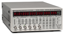
This range comprises the DG645 and DG535 programmable digital delay and pulse generators and the DB64 passive coaxial delay box. Both digital generators provide 5 ps delay resolution for precise pulse positioning and width control. The DG645 combines four pulse outputs with trigger rates up to 10 MHz, optional access to eight individual delay events and Ethernet, GPIB and RS-232 control. The DG535 provides four independent delay outputs, two pulse channels and selectable TTL, ECL, NIM or variable output levels.
The DB64 introduces a manually selected coaxial delay from 0 to 63.5 ns in 0.5 ns increments without electrical power. Applications include laser synchronisation, automated testing, pulse generation, photomultiplier coincidence adjustment, time-to-amplitude converter set-up and signal phase control. Model selection depends on trigger rate, jitter, output configuration, remote interface and whether the delay must be programmed electronically or adjusted passively.
Range features
A high level overview of what this range offers
- 5 ps digital delay resolution on DG645 and DG535 – Enables fine adjustment of pulse position and width.
- DG645 trigger rates up to 10 MHz – Supports high-repetition timing and pulse applications.
- DG645 RMS jitter below 25 ps under stated conditions – Reduces timing uncertainty in short-delay applications.
- Four DG645 pulse outputs with optional individual delay outputs – Accommodates multi-channel timing and distribution requirements.
- DG535 logic and variable-level outputs – Interfaces with TTL, ECL, NIM and application-specific signal levels.
- Linked DG535 delay channels – Maintain a defined pulse width when pulse position is changed.
- Multiple triggering modes – Internal, external, line, single-shot and burst triggering match different test and control sequences.
- Optional high-voltage outputs – Support applications requiring higher pulse amplitudes than the standard outputs provide.
- DG645 Ethernet, GPIB and RS-232 interfaces – Enable local, computer-based and networked instrument control.
- DG535 GPIB control – Supports integration into established IEEE-488 automated test systems.
- DB64 passive coaxial delay adjustment – Introduces a controlled delay without a programmed trigger cycle or power supply.
- 50 Ω BNC signal paths – Simplify connection to common laboratory and test-system cabling.
Downloads
for Digital delay & pulse generators
What’s in this range?
All the variants in the range and a comparison of what they offer
Specifications table
| Product / parameter | Specification |
|---|---|
Range composition | DG645 and DG535 digital delay/pulse generators; DB64 passive coaxial delay box |
DG645 standard output configuration | Four independent pulse outputs controlled by eight programmed delay events |
DG645 optional delay outputs | Eight individual rear-panel delay outputs plus T₀ |
DG645 delay range | 0 to 2000 s |
DG645 delay resolution | 5 ps |
DG645 delay accuracy | 1 ns + timebase error × delay |
DG645 RMS jitter | External trigger to output: 25 ps + timebase jitter × delay; T₀ to output: 15 ps + timebase jitter × delay |
DG645 external trigger rate | DC to 1/(100 ns + longest delay), maximum 10 MHz |
DG645 prescaled trigger input | DC to 100 MHz |
DG645 internal rate generator | 100 µHz to 10 MHz with 1 µHz resolution |
DG645 burst length | 1 to 2³² − 1 delay cycles |
DG645 burst period | 100 ns to 42.9 s with 10 ns resolution |
DG645 front-panel output impedance | 50 Ω |
DG645 front-panel transition time | <2 ns |
DG645 front-panel amplitude | 0.5 to 5.0 V |
DG645 front-panel offset | ±2 VDC |
DG645 timebase options | Standard crystal, optional OCXO, optional rubidium or external 10 MHz reference |
DG645 interfaces | GPIB IEEE-488.2, RS-232 and Ethernet |
DG645 configuration memory | Nine non-volatile instrument configurations |
DG645 power | <100 W; 90 to 264 VAC; 47 to 63 Hz |
DG645 dimensions | 8.5 × 3.5 × 13 in, W × H × D |
DG645 weight | 9 lb |
DG535 standard output configuration | Four independent delay outputs and two independent pulse channels with complementary outputs |
DG535 delay range | 0 to 999.999999999995 s |
DG535 delay resolution | 5 ps |
DG535 delay accuracy | 1500 ps + timebase error × delay |
DG535 RMS jitter | <100 ps + 10⁻⁸ × delay; approximately 50 ps for short delays under typical conditions |
DG535 external trigger rate | DC to 1/(1 µs + longest delay) |
DG535 trigger threshold | ±2.56 VDC with 10 mV resolution |
DG535 internal rate generator | Single shot, 0.001 Hz to 1.000 MHz or line synchronised |
DG535 burst mode | 2 to 32,766 pulses at integer multiples from 4 to 32,767 of the trigger period |
DG535 output load | 50 Ω or high impedance |
DG535 typical rise time | 2 to 3 ns |
DG535 standard output levels | TTL, ECL, NIM or variable level from −3 to +4 VDC with 10 mV resolution |
DG535 timebase | Standard 25 ppm crystal, optional 1 ppm TCXO or external 10.0 MHz reference |
DG535 computer interface | GPIB IEEE-488 |
DG535 power | 70 W; 100/120/220/240 VAC; 50/60 Hz |
DG535 dimensions | 8.5 × 4.75 × 14 in, W × H × D |
DG535 weight | 10 lb |
DB64 connectors | Interchangeable BNC input and output |
DB64 impedance | 50 Ω |
DB64 delay line | RG58A/U coaxial cable |
DB64 insertion delay | 2.5 ns |
DB64 adjustable delay range | 0 to 63.5 ns |
DB64 delay resolution | 0.5 ns |
DB64 delay error | <100 ps + 0.5% of selected delay |
DB64 signal reflection | <3% |
DB64 switch feed-through | <0.8 pF |
DB64 maximum voltage | 250 Vrms |
DB64 maximum current | 2 A |
DB64 dimensions | 8.3 × 1.5 × 8.0 in, W × H × D |
DB64 weight | 2 lb |
Range comparison
| Specification | DG645 | DG535 | DB64 |
|---|---|---|---|
Product identifier | DG645 | DG535 | DB64 |
Product type | Programmable digital delay and pulse generator | Programmable digital delay and pulse generator | Passive coaxial delay box |
Standard timing outputs | Four pulse outputs from eight programmed delay events | Four delay outputs and two independent pulse channels | One bidirectional coaxial signal path |
Delay range | 0 to 2000 s | 0 to approximately 1000 s | 0 to 63.5 ns adjustable delay, plus 2.5 ns insertion delay |
Resolution | 5 ps | 5 ps | 0.5 ns |
Maximum trigger rate | 10 MHz direct; synchronisation to 100 MHz with prescaling | 1 MHz internal | Not applicable to the passive signal path |
Timing uncertainty | <25 ps RMS headline jitter under stated conditions | <100 ps RMS plus delay-dependent contribution | Delay error <100 ps + 0.5% of selected delay |
Signal interface | 50 Ω BNC pulse outputs | 50 Ω or high-impedance BNC outputs | 50 Ω BNC input/output |
Remote control | Ethernet, GPIB and RS-232 | GPIB | Manual switches only |
Electrical power | 90 to 264 VAC | Selectable 100/120/220/240 VAC | No external power required |
FAQs
for Digital delay & pulse generators
Choose the DG645 when the system requires trigger rates up to 10 MHz, four programmable pulse outputs, optional access to eight individual delay events or Ethernet and RS-232 control. The DG535 is appropriate where four delay outputs, two pulse channels, a maximum internal rate of 1 MHz and GPIB automation meet the timing requirement. Both instruments provide 5 ps delay resolution, but their jitter, timebase choices and interface options differ. The DB64 serves a different purpose by adding up to 63.5 ns of passive coaxial delay in 0.5 ns increments. Selection should therefore begin with the required timing architecture rather than delay resolution alone.
The DG645 is intended for applications with tighter short-term timing requirements, with headline RMS jitter below 25 ps under stated trigger conditions. Its specified external-trigger timing uncertainty is 25 ps plus the timebase-jitter contribution multiplied by the programmed delay, while T₀-to-output jitter is 15 ps plus that contribution. The DG535 specifies less than 100 ps plus 10⁻⁸ multiplied by the delay, with approximately 50 ps typical jitter for short delays. At longer delays, the selected timebase increasingly affects both instruments. Engineers should also account for trigger noise, impedance matching and measurement-instrument jitter when validating overall system performance.
The optional DG645 timebases become relevant when timing accuracy must be maintained over long programmed delays or extended calibration intervals. For a 1 s delay one year after calibration, the stated timing error can reach approximately 5 µs with the standard timebase, 200 ns with the OCXO and 500 ps with the rubidium option. These differences are much less important when only short relative delays are being generated and both edges use the same timing reference. The DG535 provides a standard 25 ppm crystal, an optional 1 ppm TCXO and support for an external 10 MHz reference. Timebase selection should therefore be based on absolute delay accuracy and ageing requirements, not solely on short-delay jitter.
The DG645 front-panel outputs use a 50 Ω source impedance, provide amplitudes from 0.5 to 5.0 V, permit offsets over ±2 VDC and have transition times below 2 ns. Its optional rear-panel configurations provide either 5 V delay outputs, combinatorial 5 V outputs or pulses up to 30 V into high impedance and 15 V into 50 Ω. The DG535 can operate into 50 Ω or high-impedance loads and provides TTL, ECL, NIM or variable levels from −3 to +4 VDC. A rear-panel option extends the DG535 output range to approximately ±32 V. The load, cable impedance, required transition time and pulse repetition rate must all be checked before choosing an output option.
The DG645 internal rate generator spans 100 µHz to 10 MHz with 1 µHz resolution, while its direct external trigger input operates up to 10 MHz. Prescaling allows it to remain synchronised with sources operating as fast as 100 MHz, which is useful when deriving lower repetition rates from a mode-locked laser or another high-frequency clock. It also supports holdoff and burst lengths from one to 2³² − 1 cycles. The DG535 operates internally from 0.001 Hz to 1 MHz and provides bursts of 2 to 32,766 pulses. The DG645 therefore offers more flexibility where high source rates, large burst counts or per-output prescaling form part of the timing sequence.
The DG645 provides Ethernet, GPIB IEEE-488.2 and RS-232 interfaces, allowing all instrument functions to be controlled remotely. Nine complete instrument configurations can be retained in non-volatile memory, reducing set-up time when a test station runs several timing profiles. The DG535 provides GPIB IEEE-488 control and also stores nine user configurations, with a separate default configuration available for recall. This makes the DG535 compatible with established GPIB-based systems, while the DG645 offers more connection choices for newer networked installations. The DB64 has no electronic control interface because its delay is selected directly with mechanical switches.
The DB64 should be considered when a signal needs a fixed, manually adjustable propagation delay rather than a newly generated logic pulse. Its delay can be set from 0 to 63.5 ns in 0.5 ns increments, with a fixed insertion delay of 2.5 ns. Delay error is below 100 ps plus 0.5% of the selected delay, signal reflection is below 3% and switch feed-through is below 0.8 pF. The 50 Ω RG58A/U path can carry signals up to 250 Vrms or 2 A within the stated limits. This arrangement supports coincidence timing, phase adjustment and time-to-amplitude converter set-up without introducing a trigger-processing stage.
The DG645 measures 8.5 × 3.5 × 13 in, weighs 9 lb and accepts 90 to 264 VAC at 47 to 63 Hz with power consumption below 100 W. The DG535 measures 8.5 × 4.75 × 14 in, weighs 10 lb and uses selectable 100, 120, 220 or 240 VAC input at 50 or 60 Hz, with 70 W consumption. Correct line-voltage and fuse selection is required when installing the DG535. The passive DB64 measures 8.3 × 1.5 × 8.0 in, weighs 2 lb and requires no mains connection. Two DB64 units can be installed side by side in a 19 in rack using the designated rack accessory.