Cavity Bandpass Filters
- Technology
- RF Filters
- Partner
- Sangshin
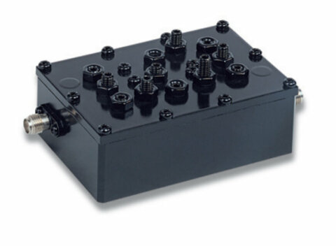
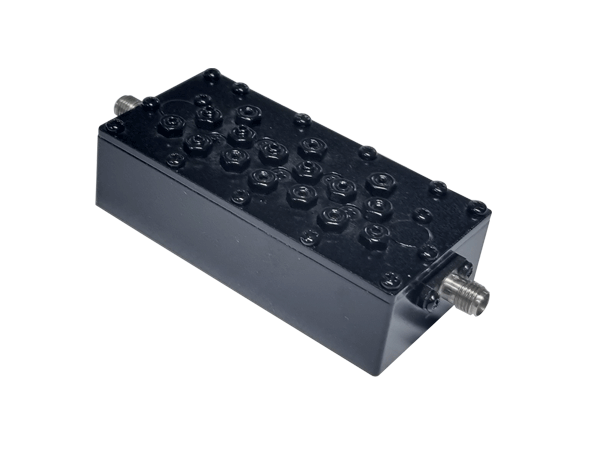
Cavity bandpass filters pass a selected operating band while attenuating frequencies outside it. The CABPF range gives RF engineers a choice of narrowband and broadband variants covering passband limits from 400 MHz to 9.8 GHz. Each of the 42 listed models has one frequency path, together with model-specific electrical and mechanical characteristics. Maximum insertion loss ranges from 0.5 to 3.5 dB, while minimum return loss values extend from 12 to 18 dB. Stopband attenuation reaches 80 dB at defined frequencies on selected variants. Potential applications include mobile communications, 5G infrastructure, TRS, GPS, WLAN, RFID, Wi‑Fi and other radio systems, subject to the requirements of the selected model. Selection should consider the required passband, rejection frequencies, permissible signal loss and available installation space.
Range features
A high level overview of what this range offers
- 42 filter variants – Provides a broad choice of centre frequencies, bandwidths and rejection profiles.
- 403 MHz to 9.65 GHz centre-frequency coverage – Supports RF designs ranging from UHF to microwave frequencies.
- Single frequency path – Provides a defined bandpass function for each listed model.
- Maximum insertion loss from 0.5 to 3.5 dB – Allows engineers to account for filter loss within the RF link budget.
- Minimum return loss from 12 to 18 dB – Provides model-level matching data for system integration.
- Stopband attenuation up to 80 dB – Supports suppression of specified out-of-band signals.
- Narrowband and broadband configurations – Enables selection for channel-specific or wider operating bands.
- Multiple mechanical formats – Allows dimensions to be compared against enclosure and installation constraints.
- Defined rejection frequencies – Helps engineers evaluate nearby-channel, harmonic and out-of-band suppression requirements.
What’s in this range?
All the variants in the range and a comparison of what they offer
| Part No. | Classification | Normalised Technology | Band | Frequency Paths | Start Freq. [MHz] | Center Freq. [MHz] | Stop Freq. [MHz] | Insertion Loss [dB/max.] | Return Loss [dB/min.] | Ripple [dB/max.] | Attenuation [dB/min.] | Dimensions (L × W × H) [mm] |
|---|---|---|---|---|---|---|---|---|---|---|---|---|
CABPF12MR3550S500SA | Cavity | Cavity | 1 | 3300 | 3550 | 3800 | 2 | 14 | 50 @ 1 ~ 2690 25 @ 2690 ~ 3250 25 @ 3850 ~ 4200 50 @ 4400 ~ 6000 | 100 × 40 × 23 | ||
CABPF14MR3750S900SA | Cavity | Cavity | 1 | 3300 | 3750 | 4200 | 2 | 14 | 50 @ 1 ~ 2690 25 @ 2690 ~ 3200 40 @ 4400 ~ 6000 | 88 × 50 × 23 | ||
CABPF14MR4077S320A | Cavity | Cavity | 77 | 1 | 3917 | 4077 | 4237 | 1.8 | 15 | 75 @ 3877 & 4277 | 140 × 45 × 20 | |
CABPF3MR1296.250S0.5NA | Cavity | Cavity | 1 | 1296 | 1296.5 | 1296.25 | 3 | 18 | 30 @ 1304.5 ~ 1307 30 @ 1265 ~ 1266 | 69 × 59 × 45 | ||
CABPF3MR1296S1NA | Cavity | Cavity | 1 | 1295.5 | 1296 | 1296.5 | 3 | 18 | 25 @ 1304 ~ 1307 25 @ 1255 ~ 1256 | 69 × 59 × 45 | ||
CABPF4MR2355S10SA | Cavity | Cavity | 1 | 2350 | 2355 | 2360 | 2 | 14 | 45 @ 10 ~ 2180 75 @ 2305 ~ 2315 45 @ 2700 ~ 5000 | 59.5 × 46 × 26 | ||
CABPF4MR5487.5S775A | Cavity | Cavity | 1 | 5100 | 5487.5 | 5875 | 0.75 | 15 | 40 @ 0 ~ 2500 30 @ 10200 ~ 29375 | 50 × 50 × 22 | ||
CABPF4MR866S2A | Cavity | Cavity | 1 | 865 | 866 | 867 | 3 | 14 | 40 @ 872 | 64 × 52 × 43 | ||
CABPF4MR9866S2A | Cavity | Cavity | 1 | 865 | 866 | 867 | 3 | 14 | 40 @ 872 | 64 × 52 × 43 | ||
CABPF5MR1340S120A | Cavity | Cavity | 1 | 1280 | 1340 | 1400 | 0.5 | 18 | 30 @ 1140 30 @ 1540 | 92 × 61 × 46 | ||
CABPF5MR1621P10A | Cavity | Cavity | 1 | 1616 | 1621.25 | 1626.5 | 3.5 | 14.5 | 1 | 35 @ 1609.5 45 @ 1635 | 44 × 85 × 30 | |
CABPF5MR2310S10SA | Cavity | Cavity | 1 | 2305 | 2310 | 2315 | 3 | 14 | 45 @ 10 ~ 2180 75 @ 2350 ~ 2360 45 @ 2700 ~ 5000 | 64 × 42 × 26 | ||
CABPF5MR403N6A | Cavity | Cavity | 1 | 400 | 403 | 406 | 2 | 13.98 | 1 | 20 @ 397 20 @ 409 | 135 × 88 × 84 | |
CABPF5MR403N6B | Cavity | Cavity | 1 | 400 | 403 | 406 | 3 | 13.98 | 1 | 20 @ 397 20 @ 409 | 135 × 93 × 84 | |
CABPF5MR403N6C | Cavity | Cavity | 1 | 400 | 405 | 410 | 3 | 13.98 | 1 | 20 @ 397 20 @ 413 | 135 × 93 × 84 | |
CABPF5MR4881S10B | Cavity | Cavity | 1 | 4876.55 | 4881.55 | 4886.55 | 3 | 16 | 55 @ fc±75 | 80 × 28 × 18.5 | ||
CABPF5MR4995P90A | Cavity | Cavity | 1 | 4950 | 4995 | 5040 | 2 | 14 | 40 @ 5098MHz ~ 8GHz 40 @ 4895MHz ~ 1GHz | 57 × 15 × 20 | ||
CABPF5MR5170S160A | Cavity | Cavity | 1 | 5090 | 5170 | 5250 | 1 | 16 | 30 @ 5000 30 @ 5350 ~ 12000 | 60 × 45 × 21 | ||
CABPF5MR5787NA | Cavity | Cavity | 1 | 5720 | 5787.5 | 5855 | 1 | 15 | 0.5 | 80 @ 100 ~ 4000 50 @ 5500 50 @ 6100 | 68 × 69 × 22 | |
CABPF5MR8212SA | Cavity | Cavity | 1 | 8087.5 | 8212.5 | 8337.5 | 1 | 15 | 20 @ 8400 | 45 × 26 × 15 | ||
CABPF6MR2350S100A | Cavity | Cavity | 1 | 2300 | 2350 | 2400 | 2 | 14 | 10 @ 10 ~ 700 25 @ 700 ~ 2170 13 @ 2170 ~ 2280 13 @ 2420 ~ 2495 25 @ 2495 ~ 2700 | 65 × 36 × 24 | ||
CABPF6MR2395S10A | Cavity | Cavity | 1 | 2390 | 2395 | 2400 | 1.3 | 18 | 55 @ fc±20 | 142 × 97 × 34 | ||
CABPF6MR2595S50A | Cavity | Cavity | 1 | 2570 | 2595 | 2620 | 2 | 14 | 10 @ 10 ~ 700 25 @ 700 ~ 2400 15 @ 2400 ~ 2495 13 @ 2495 ~ 2560 33 @ 2630 ~ 2670 | 65 × 36 × 24 | ||
CABPF6MR3637.5S325A | Cavity | Cavity | 1 | 3475 | 3637.5 | 3800 | 0.5 | 18 | 25 @ 3275 15 @ 3375 15 @ 3900 25 @ 4000 40 @ 4100 | 103 × 24 × 24 | ||
CABPF6MR8212SA | Cavity | Cavity | 1 | 8087.5 | 8212.5 | 8337.5 | 1 | 15 | 50 @ 8400 ~ 8450 | 60 × 32 × 16 | ||
CABPF6MR8212SB | Cavity | Cavity | 1 | 8087.5 | 8212.5 | 8337.5 | 1 | 15 | 50 @ 8400 ~ 8450 | 60 × 32 × 17 | ||
CABPF7MR1375S50A | Cavity | Cavity | 1 | 1350 | 1375 | 1400 | 1 | 18 | 60 @ fc±50 40dB @ 2fc and 3fc | 118 × 57 × 39 | ||
CABPF7MR3500S200B | Cavity | Cavity | 1 | 3400 | 3500 | 3600 | 2 | 14 | 45 @ 10 ~ 2700 30 @ 3610 ~ 3800 45 @ 4000 ~ 5000 | 74 × 36 × 24 | ||
CABPF7MR3550S500SA | Cavity | Cavity | 1 | 3300 | 3550 | 3800 | 2 | 14 | 50 @ 1 ~ 2690 25 @ 2690 ~ 3250 20 @ 3850 ~ 4200 40 @ 4400 ~ 6000 | 74 × 32.8 × 23 | ||
CABPF7MR3700S200A | Cavity | Cavity | 1 | 3600 | 3700 | 3800 | 2 | 14 | 45 @ 10 ~ 2700 30 @ 3400 ~ 3590 45 @ 4000 ~ 5000 | 74 × 36 × 24 | ||
CABPF7MR4300S200A | Cavity | Cavity | 1 | 4200 | 4300 | 4400 | 0.8 | 18 | 50 @ 3700 ~ 3980 50 @ 4600 ~ 7000 | 97.5 × 35.1 × 25 | ||
CABPF7MR879.7S20A | Cavity | Cavity | 1 | 869.7 | 879.7 | 889.7 | 3 | 18 | 45 @ 893.2 ~ 899.7 | 70 × 80 × 35 | ||
CABPF7MR915N25A | Cavity | Cavity | 1 | 902 | 914.5 | 927 | 2 | 15 | 20 @ 929 ~ 931 | 132 × 65 × 57 | ||
CABPF7MR9650S300A | Cavity | Cavity | 1 | 9500 | 9650 | 9800 | 1.5 | 15 | 60 @ 9100 60 @ 10200 | 60 × 30 × 16 | ||
CABPF8MR1372S45A | Cavity | Cavity | 1 | 1350 | 1372.5 | 1395 | 1 | 18 | 15 @ 1400 ~ 1427 60 @ fc±50 40 @ 2fc and 3fc | 135 × 65 × 33 | ||
CABPF8MR1747S75A | Cavity | Cavity | 1 | 1710 | 1747.5 | 1785 | 2 | 14 | 50 @ 10 ~ 1000 30 @ 1000 ~ 1500 75 @ 1805 ~ 1880 45 @ 1930 ~ 2700 | 65 × 55 × 35 | ||
CABPF8MR1842S75A | Cavity | Cavity | 1 | 1805 | 1842.5 | 1880 | 2 | 14 | 50 @ 10 ~ 1000 30 @ 1000 ~ 1500 75 @ 1710 ~ 1785 45 @ 1930 ~ 2700 | 65 × 55 × 35 | ||
CABPF8MR2593S194A | Cavity | Cavity | 1 | 2496 | 2593 | 2690 | 2 | 14 | 10 @ 10 ~ 700 25 @ 700 ~ 2400 15 @ 2400 ~ 2482 15 @ 2700 ~ 4000 | 82 × 36 × 24 | ||
CABPF8MR3625P150A | Cavity | Cavity | 1 | 3550 | 3625 | 3700 | 2.5 | 15 | 1.5 | 60 @ 1 ~ 3300 20 @ 3301 ~ 3530 20 @ 3720 ~ 3750 60 @ 3750 ~ 12000 | 63 × 28 × 16 | |
CABPF9MR2800S200A | Cavity | Cavity | 1 | 2700 | 2800 | 2900 | 1 | 18 | 30 @ 2650 30 @ 2950 | 50 × 42 × 30 | ||
CABPF9MR3500S100A | Cavity | Cavity | 1 | 3450 | 3500 | 3550 | 2 | 12 | 60 @ 608 ~ 3300 24 @ 3300 ~ 3430 9 @ 3430 ~ 3440 9 @ 3560 ~ 3570 24 @ 3570 ~ 4200 | 72 × 72 × 25 | ||
CABPF9MR4500S200A | Cavity | Cavity | 1 | 4400 | 4500 | 4600 | 2 | 14 | 55 @ 1100 ~ 4310 55 @ 4690 ~ 8000 | 77 × 77 × 20 |
FAQs
for Cavity Bandpass Filters
Start by matching the required start, centre and stop frequencies. Then compare insertion loss, return loss, rejection frequencies, attenuation and physical dimensions against the RF link budget and mechanical design.
The listed passband limits extend from 400 MHz to 9.8 GHz, with centre frequencies ranging from 403 MHz to 9.65 GHz. Coverage varies by part number rather than being continuously tunable.
Maximum insertion loss ranges from 0.5 to 3.5 dB across the listed variants. The value for the selected part should be included in the receiver sensitivity, transmitter output or overall link-budget calculation.
Attenuation is defined at model-specific frequencies and reaches 80 dB on selected variants. Engineers should compare the stated rejection points directly with expected interferers, adjacent channels and harmonic frequencies.
Yes. Narrowband options include filters with passbands of only a few megahertz, such as the 1295.5–1296.5 MHz and 865–867 MHz variants. Wider models are also available for broader operating bands.
Several variants cover frequencies used by sub-6 GHz radio infrastructure, including passbands around 3.3–4.4 GHz. Suitability depends on the required channel bandwidth, rejection mask, insertion loss, power level, interface and environmental conditions.
Each variant includes length, width and height in millimetres. Connector orientation, mounting-hole details and interface drawings are not included in the listed specifications and should be confirmed during mechanical design.
Impedance, connector type, maximum RF power, operating temperature and environmental ratings are not included in the available specifications. These parameters should be confirmed before a filter is approved for a production design.