SIW Bandpass Filters
- Technology
- RF Filters
- Partner
- Sangshin
The SIW bandpass filter range comprises four single-path RF filters for frequency-selective signal paths at 27, 28.5, 29 and 38.1 GHz. The available models address Bands 257, 260 and 261, providing options across several high-frequency wireless allocations. Each filter has defined start, centre and stop frequencies, together with maximum insertion loss, minimum return loss, maximum ripple and out-of-band attenuation values. The three models covering 27 to 29 GHz share dimensions of 6 × 14.76 × 0.51 mm, while the 38.1 GHz model measures 3.84 × 10.86 × 0.81 mm. These SIW bandpass filters can be used in wireless communication equipment requiring a single passband within the specified operating frequencies. Engineers can select a model according to the required passband, attenuation point, insertion-loss budget and available board space.
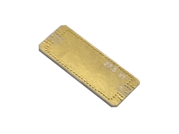
These SIW bandpass filters provide four single-path options for RF designs operating at 27, 28.5, 29 and 38.1 GHz. The range covers Bands 257, 260 and 261, with 500 MHz or 1 GHz passbands depending on the selected model. Each part is specified with defined passband limits, insertion loss, return loss, ripple and out-of-band attenuation to support frequency-selective wireless communication designs.
The 27 to 29 GHz variants share a compact 6 × 14.76 × 0.51 mm footprint, while the 38.1 GHz model uses a smaller 3.84 × 10.86 × 0.81 mm package. This allows engineers to choose a filter based on electrical targets as well as available PCB space.
Range features
A high level overview of what this range offers
- Four centre-frequency options: Supports RF designs operating at 27, 28.5, 29 or 38.1 GHz.
- Bands 257, 260 and 261 covered: Provides model options for several high-frequency wireless signal paths.
- 500 MHz or 1 GHz passbands: Enables selection according to the required operating bandwidth.
- Single frequency path: Suits applications requiring one defined passband rather than duplexed or multiplexed operation.
- 10 dB minimum return loss: Provides a consistent quantified matching criterion across all four models.
- 0.8 to 1.2 dB maximum ripple: Allows passband amplitude variation to be considered during RF system design.
- Specified out-of-band attenuation: Supports rejection analysis at defined frequencies outside the operating passband.
- Model-specific package dimensions: Allows mechanical selection against the available PCB area and height.
What’s in this range?
All the variants in the range and a comparison of what they offer
| Part No. | Classification | Normalised Technology | Band | Frequency Paths | Start Freq. [MHz] | Center Freq. [MHz] | Stop Freq. [MHz] | Insertion Loss [dB/max.] | Return Loss [dB/min.] | Ripple [dB/max.] | Attenuation [dB/min.] | Dimensions (L × W × H) [mm] |
|---|---|---|---|---|---|---|---|---|---|---|---|---|
SBP27GSP500B | SIW | SIW | 257 | 1 | 26.75 GHz | 27 GHz | 27.25 GHz | 4.5 | 10 | 0.8 | 25 @ 28750 ~ 29250 | 6 × 14.76 × 0.51 |
SBP28.5GSP1000A | SIW | SIW | 261 | 1 | 28 GHz | 28.5 GHz | 29 GHz | 4.7 | 10 | 1 | 35 @ 26500 25 @ 30500 | 6 × 14.76 × 0.51 |
SBP29GSP500A | SIW | SIW | 257 | 1 | 28.75 GHz | 29 GHz | 29.25 GHz | 4.5 | 10 | 0.8 | 28 @ 26750 ~ 27250 | 6 × 14.76 × 0.51 |
SBP38GSP1000A | SIW | SIW | 260 | 1 | 37.6 GHz | 38.1 GHz | 38.6 GHz | 5.5 | 10 | 1.2 | 50 @ 35100 | 3.84 × 10.86 × 0.81 |
FAQs
for SIW Bandpass Filters
The four available centre frequencies are 27 GHz, 28.5 GHz, 29 GHz and 38.1 GHz. Each centre frequency is associated with a separate part number and passband.
SBP27GSP500B and SBP29GSP500A are assigned to Band 257. Their respective centre frequencies are 27 GHz and 29 GHz, and both have a 500 MHz passband between the stated start and stop frequencies.
SBP28.5GSP1000A covers 28 to 29 GHz, while SBP38GSP1000A covers 37.6 to 38.6 GHz. Both therefore have a 1 GHz difference between their specified start and stop frequencies.
SBP27GSP500B and SBP29GSP500A have a maximum insertion loss of 4.5 dB. SBP28.5GSP1000A is rated at 4.7 dB maximum, while SBP38GSP1000A is rated at 5.5 dB maximum.
Yes. Each model has a specified minimum return loss of 10 dB.
The 27, 28.5 and 29 GHz models measure 6 × 14.76 × 0.51 mm. The 38.1 GHz model has a smaller length and width but greater height, measuring 3.84 × 10.86 × 0.81 mm.
The stated minimum attenuation ranges from 25 to 50 dB, depending on the model and test frequency. Engineers should compare the specified attenuation points with the expected interfering frequencies in their RF design.
Every model has one frequency path. The range data does not describe duplexing, multiplexing or multiple simultaneous passbands.
The SIW bandpass filters cover Bands 257, 260 and 261 and can support wireless communication designs where their passband and rejection characteristics match the system requirements. Suitability should also be checked against electrical and environmental parameters required by the final application.
The available range data does not include characteristic impedance, power handling, operating temperature, termination style, PCB land pattern or environmental qualification details. These parameters should be confirmed before completing an RF or mechanical design.