RF Duplexers
- Technology
- RF Filters
- Partner
- Sangshin
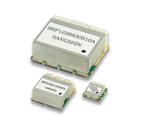
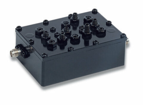
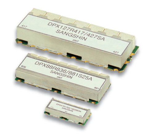
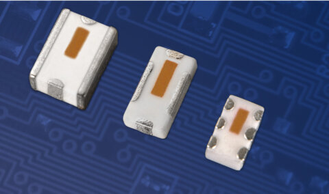
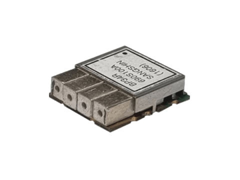
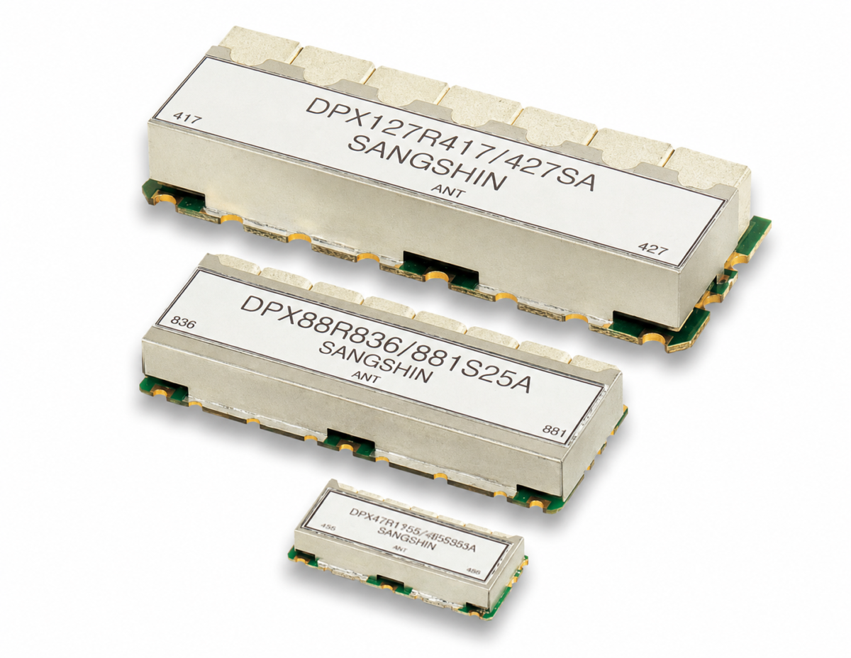
These RF duplexers provide two frequency paths for applications that require defined passbands and attenuation between separate operating bands. The range covers cavity, LC, discrete and ceramic monoblock technologies, allowing engineers to compare different electrical and mechanical configurations. Available frequency boundaries extend from 0.1 MHz to 7125 MHz across the listed variants. Options are provided for cellular infrastructure, LTE and 5G equipment, GPS, WLAN, Wi-Fi, RFID, TRS and other radio communication systems. Each part includes dimensional information to support enclosure, PCB and system-level integration work. Electrical selection can be based on start, centre and stop frequencies together with insertion loss, return loss, ripple and attenuation requirements. The appropriate variant will depend on the required frequency pairing, isolation, passband response and available installation space.
Range features
A high level overview of what this range offers
- Cavity, LC, discrete and ceramic monoblock options – Supports selection according to electrical, dimensional and integration requirements.
- Two frequency paths per duplexer – Routes a pair of specified operating bands through one duplexing component.
- Overall frequency boundaries from 0.1 MHz to 7125 MHz – Provides options for a broad range of radio and telecommunications designs.
- Maximum insertion loss values from 1 dB to 4 dB – Enables passband-loss comparison between variants.
- Minimum return loss values from 10 dB to 20 dB – Helps engineers assess impedance matching within the passbands.
- Specified attenuation from 15 dB to 80 dB minimum – Supports comparison of out-of-band rejection and path isolation.
- Ripple values supplied for applicable models – Allows passband-flatness requirements to be considered during selection.
- Dimensions listed for every variant – Simplifies mechanical and enclosure compatibility checks.
- Multiple band-specific configurations – Supports selection for cellular, navigation and wireless communication equipment.
What’s in this range?
All the variants in the range and a comparison of what they offer
| Part No. | Classification | Normalised Technology | Band | Frequency Paths | Start Freq. [MHz] | Center Freq. [MHz] | Stop Freq. [MHz] | Insertion Loss [dB/max.] | Return Loss [dB/min.] | Ripple [dB/max.] | Attenuation [dB/min.] | Dimensions (L × W × H) [mm] |
|---|---|---|---|---|---|---|---|---|---|---|---|---|
CADPX10MR766/796S17A | Cavity | Cavity | 2 | 758 | 766.5 | 775 | 1 | 17 | 0.5 | 55 @ 788 ~ 805 | 153 × 70 × 51 | |
CADPX10MR932/941NA | Cavity | Cavity | 2 | 828 | 828.5 | 829 | 1.5 | 17 | 0.5 | 70 @ 952 ~ 953 | 134 × 75 × 54 | |
CADPX12MR2045S60A | Cavity | Cavity | 2 | 1920 | 1950 | 1980 | 2 | 20 | 75 @ 2110 ~ 2170 | 84 × 84 × 38 | ||
CADPX14MR1880/1960S60A | Cavity | Cavity | 2 | 1850 | 1880 | 1910 | 1.5 | 15 | 1 | 52 @ DC ~ 1747.5 10 @ 1790 ~ 1825 62 @ 1930 ~ 2332.5 70 @ 2332.5 ~ 2387.5 52 @ 2387.5 ~ 6000 | 177.8 × 82.6 × 38.1 | |
CADPX6MR811/856S10A | Cavity | Cavity | 2 | 806 | 811 | 816 | 1 | 17 | 0.5 | 55 @ 851 ~ 861 | 100 × 67 × 57 | |
CADPX6MR850/934N2A | Cavity | Cavity | 2 | 849 | 850 | 851 | 1.5 | 17 | 0.5 | 70 @ 933 ~ 935 | 120 × 75.6 × 54 | |
CADPX8MR757/787N1A | Cavity | Cavity | 2 | 757 | 757.5 | 758 | 1.2 | 17 | 0.5 | 80 @ 787 ~ 788 | 134 × 75.6 × 53.4 | |
CADPX8MR928/952N1A | Cavity | Cavity | 2 | 928 | 928.5 | 929 | 1.5 | 17 | 0.5 | 70 @ 952 ~ 953 | 134 × 75.6 × 54 | |
DPX153/431SAP | LC | LC | 2 | 67 | 153.5 | 240 | 1.5 | 15 | 0.35 | 35 @ 350 ~ 512 | 28 × 30 × 7.5 | |
DPX431/829SAP | LC | LC | 2 | 350 | 431 | 512 | 2 | 15 | 0.45 | 35 @ 698 ~ 960 | 28 × 30 × 7.5 | |
DPX44R1227/1575S20B | Discrete | Discrete | L2 | 2 | 1217.6 | 1227.6 | 1237.6 | 1.5 | 12 | 0.4 | 35 @ 1575.4 | 15.5 × 18.3 × 5.5 |
DPX68R390/450HAP | Discrete | Discrete | 2 | 380 | 390 | 400 | 2 | 16 | 0.5 | 35 @ 430 ~ 470 | 74.5 × 86 × 16.5 | |
DPX730/833SDP | Mono | Ceramic Monoblock | 2 | 663 | 730.5 | 798 | 3 | 10 | 2 | 17 @ 817 ~ 849 | 25 × 60.5 × 6 | |
MDPX1000-2595SAP | LC | LC | 41 | 2 | 0.1 | 500 | 1000 | 1 | 16 | 1 | 20 @ 2500 ~ 2690 | 21.5 × 35 × 9.35 |
MDPX1012R1745/2145S70D | Mono | Ceramic Monoblock | 66 | 2 | 1710 | 1745 | 1780 | 1.5 | 12 | 1.6 | 68 @ 2110 ~ 2180 | 12 × 61.9 × 10.3 |
MDPX1012R1745/2155SC | Mono | Ceramic Monoblock | 66 | 2 | 1710 | 1745 | 1780 | 1.6 | 12 | 68 @ 2110 ~ 2200 | 12 × 63 × 10.3 | |
MDPX1012R751/782S11B | Mono | Ceramic Monoblock | 13 | 2 | 746 | 751.5 | 757 | 2.5 | 15 | 0.8 | 65 @ 776 ~ 787 | 10.4 × 63 × 10.3 |
MDPX1110R1546/1650S57/48A | Mono | Ceramic Monoblock | 24 | 2 | 1518 | 1546.5 | 1575 | 1.8 | 14 | 0.6 | 62 @ 1626.5 ~ 1675 | 11 × 54 × 11.6 |
MDPX1212R412/422CP05A | Mono | Ceramic Monoblock | 2 | 410 | 412.5 | 415 | 4 | 14 | 1.5 | 40 @ 420 ~ 425 | 26 × 67.15 × 14.7 | |
MDPX1212R836/881S25AP | Mono | Ceramic Monoblock | 5 | 2 | 824 | 836.5 | 849 | 2 | 14 | 1 | 50 @ 869 ~ 894 | 13.9 × 60 × 12.9 |
MDPX1412R382/392SP05A | Mono | Ceramic Monoblock | 2 | 380 | 382.5 | 385 | 3 | 15 | 1 | 55 @ 390 ~ 395 | 22 × 80 × 15.9 | |
MDPX38R5250/5800SA | Mono | Ceramic Monoblock | 46 | 2 | 5150 | 5250 | 5350 | 2 | 12 | 1 | 50 @ 5725 ~ 5875 | 5.4 × 15.8 × 3.8 |
MDPX38R6400/7000SA | Mono | Ceramic Monoblock | 96 | 2 | 6275 | 6400 | 6525 | 2.5 | 12 | 1 | 30 @ 5150 ~ 5835 | 4.6 × 15.8 × 4 |
MDPX410R1542/1643SP34J | Mono | Ceramic Monoblock | 24 | 2 | 1520 | 1542 | 1559 | 2 | 18 | 0.5 | 50 @ 1626.5 ~ 1665 | 8.8 × 30 × 5.3 |
MDPX48R1455/1503SP15A | Mono | Ceramic Monoblock | 45 | 2 | 1447.9 | 1455.4 | 1462.9 | 2.7 | 18 | 1 | 30 @ 1495.9 ~ 1510.9 | 9.5 × 22.5 × 4.75 |
MDPX48R1950/2140SP60E | Mono | Ceramic Monoblock | 1 | 2 | 1920 | 1950 | 1980 | 2.2 | 15 | 0.5 | 42 @ 2110 ~ 2170 | 9.6 × 22.3 × 4.5 |
MDPX48R2096/2280S28B | Mono | Ceramic Monoblock | 2 | 2082 | 2096 | 2110 | 2.5 | 15 | 1 | 45 @ 2266 ~ 2294 | 6.35 × 21.8 × 4 | |
MDPX48R836/881S25L | Mono | Ceramic Monoblock | 5 | 2 | 824 | 836.5 | 849 | 2.4 | 13 | 1.5 | 43 @ 869 ~ 894 | 9.6 × 22 × 3.85 |
MDPX58R5250/5697SA | Mono | Ceramic Monoblock | 46 | 2 | 5470 | 5697.5 | 5925 | 3 | 10 | 1.5 | 25 @ 5150 ~ 5350 | 8.5 × 30 × 6.2 |
MDPX610R806/847S30D | Mono | Ceramic Monoblock | 20 | 2 | 791 | 806 | 821 | 3 | 13 | 2 | 45 @ 832 ~ 862 | 14.8 × 35 × 5.95 |
MDPX610R897/942S25B | Mono | Ceramic Monoblock | 8 | 2 | 890 | 902.5 | 915 | 2.3 | 14 | 1 | 48 @ 935 ~ 960 | 11.7 × 34.75 × 5.9 |
MDPX66R1227/1575SP24B | Mono | Ceramic Monoblock | L2 | 2 | 1215.6 | 1227.6 | 1239.6 | 1.1 | 12 | 0.5 | 30 @ 1563 ~ 1588 | 12 × 38 × 7.5 |
MDPX810R1542/1643SP34G | Mono | Ceramic Monoblock | 24 | 2 | 1525 | 1542 | 1559 | 1.5 | 18 | 0.3 | 50 @ 1626.5 ~ 1660.5 | 12.7 × 44 × 9.5 |
MDPX810R1745/2155SA | Mono | Ceramic Monoblock | 66 | 2 | 1710 | 1745 | 1780 | 2.5 | 16 | 1.3 | 45 @ 1930 ~ 2700 | 8.5 × 42 × 8.4 |
MDPX810R1747/1842S75X | Mono | Ceramic Monoblock | 3 | 2 | 1710 | 1747.5 | 1785 | 3 | 15 | 2 | 50 @ 1805 ~ 1880 | 9.5 × 42 × 8 |
MDPX810R1880/1960S61A | Mono | Ceramic Monoblock | 2 | 2 | 1850 | 1880 | 1911 | 3 | 14 | 1.9 | 45 @ 1930 ~ 1990 | 9.9 × 42 × 8.2 |
MDPX810R1950/2140S60I | Mono | Ceramic Monoblock | 1 | 2 | 1920 | 1950 | 1980 | 2 | 15 | 1 | 50 @ 2110 ~ 2170 | 9 × 42 × 8.4 |
MDPX810R2535/2655SP70L | Mono | Ceramic Monoblock | 7 | 2 | 2500 | 2535 | 2570 | 2 | 17 | 0.8 | 45 @ 2620 ~ 2690 | 11 × 42 × 9.5 |
MDPX810R815/860S19A | Mono | Ceramic Monoblock | 27 | 2 | 806 | 815.5 | 825 | 2 | 15 | 0.5 | 55 @ 851 ~ 870 | 14.5 × 42 × 8.4 |
MDPX812R725/780SP45C | Mono | Ceramic Monoblock | 28 | 2 | 709 | 725.5 | 748 | 3.5 | 15 | 2 | 40 @ 758 ~ 803 | 18.28 × 67.15 × 10 |
MDPX820R707/737SP18A | Mono | Ceramic Monoblock | 12 | 2 | 698 | 707 | 716 | 3.6 | 16 | 1.2 | 67 @ 728 ~ 746 | 48 × 74 × 9 |
MDPX86R978/1090SC | Mono | Ceramic Monoblock | 2 | 975.5 | 978 | 980.5 | 1 | 16 | 0.5 | 15 @ 1082.5 ~ 1097.5 | 14 × 34 × 8.8 |
FAQs
for RF Duplexers
An RF duplexer routes two specified frequency paths while providing attenuation outside the relevant passbands. It can allow two frequency bands to share part of an RF signal chain while maintaining the required separation between them.
The range includes cavity, LC, discrete and ceramic monoblock duplexers. The suitable technology depends on the required frequency response, physical size, insertion loss and attenuation characteristics.
Across the complete range, specified frequency boundaries extend from 0.1 MHz to 7125 MHz. Each part is designed for two particular frequency paths rather than continuous operation across that entire range.
Selection should begin with the required start, centre and stop frequencies for both paths. Insertion loss, return loss, passband ripple, attenuation, dimensions and any designated band number should then be checked against the system requirements.
The listed maximum insertion loss values range from 1 dB to 4 dB, depending on the part and frequency path. Where two values are shown, each value applies to its corresponding path.
Specified minimum attenuation ranges from 15 dB to 80 dB, depending on the model and evaluated frequency interval. The complete attenuation conditions should be reviewed because some variants specify several rejection ranges.
Yes. Every listed variant specifies two frequency paths, with separate start, centre and stop frequencies shown for the paired passbands.
Return loss helps indicate impedance matching within the passband, while ripple describes variation in passband amplitude. Both parameters can affect signal-chain consistency and should be considered alongside insertion loss and attenuation.
Yes. Several ceramic monoblock variants have body lengths below 10 mm, including options for frequencies extending into the multi-gigahertz region. The complete length, width and height values should be checked against the PCB layout and surrounding components.
The available frequency combinations and technologies can support designs for cellular infrastructure, LTE, 5G, GPS, WLAN, Wi-Fi, RFID, TRS and related radio systems. Compatibility depends on matching the exact passband and rejection specifications to the application.