DUPVA 1 GHz Variable-Gain Voltage Amplifiers
- Technology
- Amplifiers
- Partner
- FEMTO Messtechnik
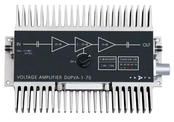
The DUPVA 1 GHz variable-gain voltage amplifier range is designed for measuring small AC signals in high-speed 50 Ω systems. It includes the DUPVA-1-60 and DUPVA-1-70, covering gain settings from 20 to 70 dB across the series in 10 dB increments. The main signal path operates from 1 kHz to 1.2 GHz, depending on the model, with bandwidth and pulse response specified as independent of the selected gain.
Typical uses include oscilloscope and transient-recorder preamplification, photomultiplier and microchannel-plate signal conditioning, optical receiver boosting and automated measurement systems. A local selector supports bench measurements, while three opto-isolated digital inputs allow external equipment to control the gain.
A separate DC to 100 kHz unity-gain monitor output provides access to low-frequency signal content alongside the wideband output. The DUPVA-1-60 provides the wider upper bandwidth and dynamic range, while the DUPVA-1-70 provides higher maximum gain and lower equivalent input noise.
Range features
A high level overview of what this range offers
- Gain settings from 20 to 70 dB across the range: Accommodate changing signal levels in selectable 10 dB increments.
- Gain-independent bandwidth and pulse response: Maintain consistent timing behavior when the gain setting changes.
- Bandwidth from 1 kHz to 1.2 GHz: Supports pulse, transient and broadband AC measurements.
- Gain flatness of ±0.15 dB: Limits amplitude variation through the specified passband.
- Rise and fall times of 380 or 390 ps: Support time-resolved measurement of fast signal transitions.
- Equivalent input noise down to 330 pV/√Hz: Helps retain small signals at the highest gain setting.
- 50 Ω SMA signal connections: Integrate directly into impedance-matched RF measurement chains.
- Local and opto-isolated remote gain control: Supports manual operation and automated test systems.
- DC to 100 kHz monitor output: Provides a separate view of slowly varying or DC signal content.
- LED gain indication and output short-circuit protection: Simplify gain verification and protect the output during connection faults.
What’s in this range?
All the variants in the range and a comparison of what they offer
General Specifications
| Specification | DUPVA series value | Conditions or notes |
|---|---|---|
Models | DUPVA-1-60 and DUPVA-1-70 | Variable-gain voltage amplifiers |
Main signal path | AC-coupled | Separate DC monitor output provided |
Test conditions | ±15 V supply, 25 °C, 50 Ω system impedance | Unless otherwise stated |
Gain increment | 10 dB | Five selectable settings per model |
Gain accuracy | ±0.1 dB between settings; ±1 dB overall | Both models |
Gain flatness | ±0.15 dB | Both models |
Lower cut-off frequency | 1 kHz | Both models |
Upper cut-off roll-off | 40 dB/octave | Both models |
Group delay | 2.2 ns | Both models |
AC input impedance | 50 Ω | Main signal input |
DC input impedance | 100 kΩ | Main signal input |
Output impedance | 50 Ω | Main signal output |
Linear output voltage | 2 V peak-to-peak at 100 MHz; 1.7 V peak-to-peak at 500 MHz | Both models |
Reverse isolation | 80 dB | Both models |
Monitor output gain | 1 | With load of at least 100 kΩ |
Monitor output impedance | 50 Ω | Designed for a load of at least 100 kΩ |
Monitor output range | ±10 V, ±25 mA | DC to 100 kHz bandwidth |
Remote control | Three opto-isolated digital inputs | TTL/CMOS-compatible |
Digital Low range | −0.8 to +0.8 V | Control input |
Digital High range | +1.8 to +12 V | Control input |
Signal connectors | SMA female input and output | 50 Ω system |
Control connector | 25-pin female Sub-D | Pins 14 to 16 select gain; pin 5 is the monitor output |
Power connector | Three-pin Series 1S fixed socket | Mating plug type FFA.1S.303.CLAC52; mating connector supplied |
Supply voltage | ±15 V | Both models |
Auxiliary outputs | ±12 V at up to 50 mA and +5 V at up to 50 mA | Available through control connector pins 1 to 4 |
Case size | 165 × 105 × 45 mm | Length × width × height |
Weight | 510 g | Both models |
Case material | Nickel-plated AlMg4.5Mn | Both models |
Operating temperature | 0 to +60 °C | Both models |
Storage temperature | −40 to +100 °C | Both models |
Output protection | Short-circuit protected | Main signal output |
Gain indication | LED | Displays selected gain setting |
Maximum signal input power | +13 dBm | For frequencies above 500 Hz |
Maximum signal input DC voltage | ±16 V | Maximum slope ±1 V/ms |
Maximum signal output reverse power | +13 dBm | Absolute maximum rating |
Maximum output reverse DC voltage | +16 V / −12 V | Maximum slope ±1 V/ms |
Maximum control input voltage | +16 V / −5 V | Absolute maximum rating |
Maximum supply voltage | ±17 V | Absolute maximum rating |
Variant Comparison
| Specification | DUPVA-1-60 | DUPVA-1-70 |
|---|---|---|
Gain settings | 20, 30, 40, 50 and 60 dB | 30, 40, 50, 60 and 70 dB |
Lower cut-off frequency | 1 kHz | 1 kHz |
Upper cut-off frequency | 1.2 GHz | 1.1 GHz |
Rise/fall time, 10% to 90% | 380 ps | 390 ps |
Gain flatness | ±0.15 dB | ±0.15 dB |
Noise figure at maximum gain | 3.0 dB at 60 dB | 1.9 dB at 70 dB |
Equivalent input noise at maximum gain | 450 pV/√Hz at 60 dB | 330 pV/√Hz at 70 dB |
Noise figure at intermediate gain | 3.5 dB at 30 to 50 dB | 2.5 dB at 40 to 60 dB |
Equivalent input noise at intermediate gain | 500 pV/√Hz at 30 to 50 dB | 400 pV/√Hz at 40 to 60 dB |
1/f noise corner | 40 kHz | 20 kHz |
P1dB output power at 100 MHz | 13 dBm | 12 dBm |
P1dB output power at 500 MHz | 10 dBm | 11 dBm |
Third-order intercept point, IP3 | 21 dBm | 20 dBm |
Dynamic range without averaging | 70 dB | 62 dB |
Input VSWR at minimum gain | 1.12:1 below 1 GHz; 1.7:1 below 2 GHz | 1.1:1 below 1 GHz; 1.2:1 below 2 GHz |
Input VSWR at higher gains | 1.2:1 below 1 GHz; 1.75:1 below 2 GHz | 1.7:1 below 1 GHz; 1.7:1 below 2 GHz |
Output VSWR | 1.77:1 below 1 GHz; 2.0:1 below 2 GHz | 1.5:1 below 1 GHz; 1.7:1 below 2 GHz |
Typical supply current | +350 mA / −100 mA | +250 mA / −100 mA |
Input and output | 50 Ω, SMA female | 50 Ω, SMA female |
Monitor output | Gain 1, DC to 100 kHz | Gain 1, DC to 100 kHz |
Remote interface | Three opto-isolated digital inputs | Three opto-isolated digital inputs |
Case size and weight | 165 × 105 × 45 mm; 510 g | 165 × 105 × 45 mm; 510 g |
Remote Gain-Control Codes
| Model | Gain | Pin 14, LSB | Pin 15 | Pin 16, MSB |
|---|---|---|---|---|
DUPVA-1-60 | 20 dB | Low | Low | Low |
DUPVA-1-60 | 30 dB | High | Low | Low |
DUPVA-1-60 | 40 dB | Low | High | Low |
DUPVA-1-60 | 50 dB | High | High | Low |
DUPVA-1-60 | 60 dB | Low | Low | High |
DUPVA-1-70 | 30 dB | Low | Low | Low |
DUPVA-1-70 | 40 dB | High | Low | Low |
DUPVA-1-70 | 50 dB | Low | High | Low |
DUPVA-1-70 | 60 dB | High | High | Low |
DUPVA-1-70 | 70 dB | Low | Low | High |
FAQs
for DUPVA 1 GHz Variable-Gain Voltage Amplifiers
Select the DUPVA-1-60 when the wider 1.2 GHz upper cut-off, 20 dB minimum gain or 70 dB dynamic range is more important. Its gain range is 20 to 60 dB, equivalent input noise reaches 450 pV/√Hz at 60 dB, and P1dB is 13 dBm at 100 MHz. Choose the DUPVA-1-70 when 70 dB maximum gain and the lower 330 pV/√Hz input noise are required, accepting a 1.1 GHz upper cut-off and 62 dB dynamic range. The DUPVA-1-70 also starts at 30 dB, so it offers less headroom for larger incoming signals. In practice, base the selection on the weakest expected signal, required headroom and highest frequency of interest rather than maximum gain alone.
Changing gain is not specified to alter the bandwidth, frequency response or pulse response of either model. Gain flatness is ±0.15 dB, group delay is 2.2 ns, and the rise/fall time remains 380 ps for the DUPVA-1-60 or 390 ps for the DUPVA-1-70. Gain accuracy is ±0.1 dB between settings and ±1 dB overall. These characteristics allow measurements taken at different gain settings to be compared without applying a separate timing correction for each setting. This is particularly useful when an automated system changes gain to capture signals with different amplitudes during the same measurement sequence.
The main signal path should be connected as a 50 Ω RF measurement chain. Both the AC input and output impedances are 50 Ω, and the signal connectors are female SMA types, so 50 Ω coaxial RF cables should be used for impedance matching and electromagnetic shielding. The DC input impedance is 100 kΩ, but this does not make the main path a DC-coupled high-impedance input because its lower cut-off frequency is 1 kHz. Input and output VSWR vary with model, frequency and gain, becoming less favorable as the operating frequency approaches 2 GHz. An SMA-to-BNC adapter is available, although additional adapters or alternative connector types can affect high-frequency signal quality.
For linear amplitude planning, both models specify 2 V peak-to-peak at 100 MHz and 1.7 V peak-to-peak at 500 MHz. The DUPVA-1-60 has a P1dB output level of 13 dBm at 100 MHz and 10 dBm at 500 MHz, while the DUPVA-1-70 is rated at 12 dBm and 11 dBm respectively. Their third-order intercept points are 21 dBm and 20 dBm, which helps assess behavior when several spectral components are present. P1dB identifies the onset of compression rather than a preferred continuous operating level. Allowing margin below the linear voltage and compression limits reduces amplitude error and provides headroom for pulse overshoot.
Remote operation uses three opto-isolated digital inputs on pins 14, 15 and 16 of the 25-pin Sub-D connector. Set the local gain selector to Ext, then apply the listed three-bit code for the required gain, with pin 14 acting as the least significant bit and pin 16 as the most significant bit. A digital Low is −0.8 to +0.8 V, while a digital High is +1.8 to +12 V. The remote bits are logically combined with the local switch setting, making the Ext position important for predictable control. A compatible USB interface is available with 16 digital outputs, three opto-isolated inputs and bus-powered operation for computer-controlled test systems.
The monitor output provides a unity-gain signal path with a bandwidth from DC to 100 kHz. It has a 50 Ω output impedance but is designed to drive a load of at least 100 kΩ, with an available range of ±10 V and ±25 mA. This output can be used to observe slowly varying signal components or baseline conditions that are rejected by the 1 kHz lower cut-off of the main wideband path. It should not be treated as a second GHz-bandwidth output or terminated directly into 50 Ω if unity gain is required. In a combined measurement system, the monitor and wideband outputs can provide separate low-frequency and transient information from the same input.
Both models require a regulated ±15 V supply, with typical current requirements of +350/−100 mA for the DUPVA-1-60 and +250/−100 mA for the DUPVA-1-70. The optional PS-15 supply accepts 100 to 240 VAC and provides ±15 VDC at up to +400/−250 mA, covering either model. Auxiliary ±12 V and +5 V outputs are available through the control connector at up to 50 mA per rail, but this additional load is excluded from the stated amplifier supply current. The operating temperature range is 0 to +60 °C, while storage is permitted from −40 to +100 °C. The unit weighs 510 g and requires a three-pin power connection, for which a mating plug is supplied.
The main signal path does not pass DC because its lower cut-off frequency is 1 kHz. Static signals and slowly changing components below this region will therefore be attenuated, even though the input has a DC impedance of 100 kΩ. Long-duration pulses can also show baseline shift or droop if their spectral content extends below the lower cut-off. Where both a fast transient and its low-frequency baseline must be observed, the main output can be combined with the separate DC to 100 kHz monitor output. Applications requiring amplified DC accuracy through the main output will need a DC-coupled amplifier architecture instead.