LIA series single board lock-in amplifier
- Technology
- Amplifiers
- Partner
- FEMTO Messtechnik
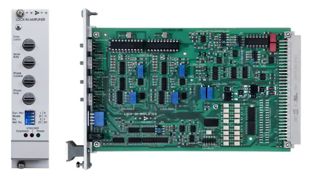
The LIA-BV(D)-150 range consists of analogue, single-board lock-in amplifiers in Eurocard format. It is designed for integration into 19-inch racks, multi-channel instruments and application-specific measurement systems. Four variants provide a choice of single- or dual-phase detection and low- or high-frequency operation. A true-differential voltage input and an inverting transimpedance current input accommodate signals from voltage-output sensors, photodetectors and other low-level sources.
Single-phase models provide an in-phase X output, while dual-phase models add quadrature Y and magnitude R outputs. Sensitivity, time constant and phase can be adjusted using local switches or controlled through opto-isolated digital inputs. Typical applications include spectroscopy, luminescence and fluorescence measurements, light scattering, optoelectronic quality control and integrated scientific instrumentation.
Range features
A high level overview of what this range offers
- Four frequency and phase variants – Match the output configuration and working range to the measurement task.
- Single- or dual-phase detection – Select an in-phase X output or X, Y and magnitude R outputs.
- 5 Hz to 120 kHz range across the series – Supports low-frequency optical measurements and higher modulation frequencies.
- 3 µV to 1 V voltage sensitivity – Accommodates a broad range of low-level voltage signals.
- 30 pA to 10 µA current sensitivity – Enables direct connection of suitable current-output detectors and sensors.
- True-differential voltage input – Supports measurements where common-mode interference must be controlled.
- 100 kV/A transimpedance current input – Converts low-current signals into a voltage for phase-sensitive detection.
- Jumper-selectable input filters – Limits unwanted frequency components before demodulation.
- Time constants with 6 or 12 dB/octave response – Provides a choice of output-filtering characteristics.
- Up to 80 dB dynamic reserve – Supports signal recovery in the presence of larger interfering components when correctly configured.
- Local and opto-isolated digital control – Enables manual operation, remote operation or a combination of both.
- Eurocard construction with 64-pin DIN connector – Supports rack backplanes and multi-board system integration.
- Optional mounting and oscillator modules – Adds hardware for 19-inch installation and reference generation.
Downloads
for LIA series single board lock-in amplifier
What’s in this range?
All the variants in the range and a comparison of what they offer
Core specifications
| Parameter | Specification |
|---|---|
Product architecture | Analogue, single-board lock-in amplifier |
Available models | LIA-BV-150-L, LIA-BV-150-H, LIA-BVD-150-L and LIA-BVD-150-H |
Form factor | 19-inch Eurocard |
Test conditions | Supply ±15 V DC; ambient temperature 25 °C |
Working frequency | 5 Hz to 10 kHz for L versions; 50 Hz to 120 kHz for H versions |
Voltage input type | True-differential instrumentation amplifier |
Voltage input full-scale range | 3 µV to 1 V in 1-3-10 steps |
Voltage input coupling | AC or DC, selected at the connector |
Voltage input impedance | 1 MΩ in parallel with 4 pF |
Voltage input noise | 12 nV/√Hz |
Common-mode rejection ratio | 110 dB at 1 kHz; 100 dB at 10 kHz |
Voltage input gain drift | 100 ppm/K |
Current input type | Inverting transimpedance amplifier |
Transimpedance gain | −100 kV/A |
Current input full-scale range | 30 pA to 10 µA in 1-3-10 steps |
Current input noise | 0.4 pA/√Hz |
Recommended current-source capacitance | 10 pF to 500 pF |
Input low-pass filter | 100 Hz, 1 kHz, 10 kHz, 100 kHz or 1 MHz; jumper-selectable; 6 dB/octave |
Input high-pass filter | L versions: 0.2 Hz, 1 Hz, 10 Hz, 100 Hz or 1 kHz; H versions: 2 Hz, 10 Hz, 100 Hz, 1 kHz or 10 kHz; 6 dB/octave |
Filter cut-off accuracy | ±20% |
Maximum dynamic reserve | 80 dB |
Demodulator dynamic reserve | 15 dB, 35 dB or 55 dB, depending on the selected operating setting |
Signal-monitor gain | 1 to 3333, dependent on gain setting |
Signal-monitor output | ±8 V maximum; 100 Ω impedance; ±10 mA maximum |
Reference input, bipolar mode | ±100 mV to ±5 V with 0 V comparator threshold |
Reference input, TTL mode | −5 V to +10 V with +2 V comparator threshold |
Reference input impedance | 1 MΩ |
Reference acquisition time | 2 s maximum in fast mode; 4 s maximum in slow mode |
Phase-shift range | 0° to 360° |
Phase resolution | L versions: 1.4°; H versions: 1.4° below 60 kHz and 2.8° above 60 kHz |
Phase-shifter drift | Less than 100 ppm/K |
Phase-shifter accuracy | Less than 0.3° |
Dual-phase orthogonality | Less than 0.1° |
Time-constant range | L versions: 3 ms to 10 s; H versions: 300 µs to 1 s; 1-3-10 steps |
Time-constant filter response | 6 or 12 dB/octave, switchable |
Output channels | BV versions: X; BVD versions: X, Y and R |
Output voltage range | ±10 V with a 2 kΩ load |
Output current | ±5 mA maximum |
Output impedance | 50 Ω |
Output DC stability | 5 ppm/K, 50 ppm/K or 500 ppm/K, depending on operating setting |
Output basic accuracy | BV: 2% for X; BVD: 2% for X and Y, 4% for R; sinusoidal input |
Output offset adjustment | ±100% of full scale using a ±10 V control signal |
Offset-control input impedance | Greater than 2 kΩ |
Digital control | Opto-isolated control of phase, time constant and sensitivity; local-control disable function |
Control input levels | Low: −0.8 V to +0.8 V; high: +1.8 V to +12 V |
Typical control input current | 0 mA at 0 V; 1.5 mA at +5 V; 4.5 mA at +12 V |
Digital status output | +4.5 V typical when active; 0 V typical when inactive; 10 mA maximum |
Status indications | Amplifier overload and reference PLL unlocked |
Supply voltage | ±15 V DC to ±18 V DC |
Supply current | L versions: −60 mA and +100 mA; H versions: −60 mA and +120 mA |
Connector | 64-pin male DIN 41612 Eurocard connector, rows a and c |
Dimensions | 160 × 100 × 20 mm |
Weight | 100 g |
Operating temperature | 0 °C to +60 °C |
Storage temperature | −40 °C to +100 °C |
Absolute maximum signal input | 50 Vpp AC; ±70 V DC |
Absolute maximum reference input | ±15 V |
Absolute maximum control input | −5 V to +15 V |
Absolute maximum supply voltage | ±22 V |
Optional mounting kit | MK-LIA-2 with 19-inch front panel and EMI-shielding board backplane |
Optional reference oscillator | SOM-1; adjustable from 5 Hz to 130 kHz and 0 to 2 Vrms |
Variant comparison
| Specification | LIA-BV-150-L | LIA-BV-150-H | LIA-BVD-150-L | LIA-BVD-150-H |
|---|---|---|---|---|
Phase detection | Single phase | Single phase | Dual phase | Dual phase |
Working frequency | 5 Hz to 10 kHz | 50 Hz to 120 kHz | 5 Hz to 10 kHz | 50 Hz to 120 kHz |
Time constants | 3 ms to 10 s | 300 µs to 1 s | 3 ms to 10 s | 300 µs to 1 s |
High-pass filter options | 0.2 Hz to 1 kHz | 2 Hz to 10 kHz | 0.2 Hz to 1 kHz | 2 Hz to 10 kHz |
Phase resolution | 1.4° | 1.4° below 60 kHz; 2.8° above 60 kHz | 1.4° | 1.4° below 60 kHz; 2.8° above 60 kHz |
Measurement outputs | X | X | X, Y and R | X, Y and R |
Output basic accuracy | 2% for X | 2% for X | 2% for X and Y; 4% for R | 2% for X and Y; 4% for R |
Phase orthogonality | Not applicable | Not applicable | Less than 0.1° | Less than 0.1° |
Supply current | −60 mA, +100 mA | −60 mA, +120 mA | −60 mA, +100 mA | −60 mA, +120 mA |
Cable selection
| Connection | Cable type | Selection basis |
|---|---|---|
Input | Low-noise cable | Mechanically disturbed environments where vibration may create triboelectric interference |
Input | RF cable | Environments exposed to electromagnetic interference |
Output | RF cable | Electromagnetic shielding and 50 Ω impedance matching |
Keep the source-to-input cable as short as practical. Where a longer connection is unavoidable in a mechanically stable environment, a lower-capacitance cable can help prevent cable capacitance from dominating the current-input load.
FAQs
for LIA series single board lock-in amplifier
Choose between BV and BVD by the output information required, then select L or H according to the modulation frequency and settling-time requirements. BV models are single-phase instruments with an X output, whereas BVD models provide X, Y and magnitude R, allowing the dual-phase versions to accommodate phase movement without relying on a single aligned channel. L versions cover 5 Hz to 10 kHz and provide time constants from 3 ms to 10 s; H versions cover 50 Hz to 120 kHz with time constants from 300 µs to 1 s. Select L for low-frequency modulation or longer averaging, and H for higher modulation rates or faster response. Confirm that the reference frequency, filter settings and required outputs all fall within the selected variant’s limits.
Yes, but the selected front end and cable capacitance must be treated as part of the measurement design. The differential voltage input covers 3 µV to 1 V full scale, offers AC or DC coupling and presents 1 MΩ in parallel with 4 pF, while the current input is an inverting 100 kV/A transimpedance stage covering 30 pA to 10 µA. Input-noise figures are 12 nV/√Hz for voltage and 0.4 pA/√Hz for current, with 10 pF to 500 pF recommended at the current input. A typical 50 Ω coaxial cable contributes about 100 pF/m, so several metres of cable can consume much of that capacitance allowance. For photodiodes or other current sources, add detector and cable capacitance together, keep the connection short and check the frequency-dependent gain error before finalising the layout.
Start with the input filters, using them to pass the modulation band while limiting unrelated low- and high-frequency components before demodulation. All variants provide 100 Hz, 1 kHz, 10 kHz, 100 kHz and 1 MHz low-pass choices, while the high-pass selections extend from 0.2 Hz to 1 kHz on L versions and from 2 Hz to 10 kHz on H versions. Post-demodulation time constants range from 3 ms to 10 s for L models and from 300 µs to 1 s for H models, with a selectable 6 or 12 dB/octave response. The series specifies up to 80 dB overall dynamic reserve, while the demodulator settings provide 15, 35 or 55 dB. In practice, choose the shortest time constant that meets the required noise bandwidth and verify settling after changing frequency, sensitivity or filter slope.
Treat the unit as a board-level Eurocard rather than a finished desktop instrument. The board measures 160 × 100 × 20 mm, weighs 100 g and uses a 64-pin male DIN 41612 connector with rows a and c for signals, supply and controls. It requires symmetrical rails between ±15 V and ±18 V; budget −60 mA and +100 mA for L variants or −60 mA and +120 mA for H variants. The optional MK-LIA-2 provides a 19-inch front panel and EMI-shielding board backplane, while the SOM-1 module can provide an adjustable reference from 5 Hz to 130 kHz. For multi-channel systems, plan rail capacity per card and maintain controlled grounding, shielding and separation between low-level analogue paths and digital-control wiring.
Sensitivity, time constant and phase can be set using the board switches or through opto-isolated digital inputs. Remote coding uses eight bits for phase, four bits for the time constant and four bits for sensitivity and dynamic-mode selection. A valid low level is −0.8 V to +0.8 V, while a high level may range from +1.8 V to +12 V; typical input current is 1.5 mA at +5 V. Remote bits are logically combined with local switch positions, so the relevant local control should be set to zero when a direct remote code is required. A separate input can disable local controls, while overload and unlocked-reference status outputs allow the host system to identify measurements that may not be valid.
The reference input accepts either a bipolar analogue signal or a TTL-compatible waveform. Bipolar mode covers ±100 mV to ±5 V with a 0 V comparator threshold, while TTL mode accepts −5 V to +10 V and uses a +2 V threshold; the input impedance is 1 MΩ. Reference acquisition takes up to 2 seconds in fast mode or 4 seconds in slow mode, so data capture should wait until the unlocked status has cleared. Phase can be adjusted across 0° to 360°, with 1.4° resolution on L models and on H models below 60 kHz, changing to 2.8° above 60 kHz. Dual-phase variants specify less than 0.1° orthogonality and are appropriate where both in-phase and quadrature information is needed.
The measurement outputs should normally feed a high-impedance acquisition input. Full-scale output is ±10 V with a 2 kΩ load, the output-current limit is ±5 mA and the stated output impedance is 50 Ω; a 50 Ω termination is therefore not compatible with full-scale ±10 V operation. BV variants provide X, while BVD variants provide X, Y and R, with basic accuracy of 2% for X and Y and 4% for R under sinusoidal input conditions. The separate monitor output reaches ±8 V, has 100 Ω impedance and permits ±10 mA. Configure the DAQ for a bipolar ±10 V range with at least the stated 2 kΩ load, and account for the output impedance if additional filtering is added. The offset input can shift the measurement output by ±100% of full scale using a ±10 V control signal.