HQA Quartz Tuning Fork Charge Amplifier
- Technology
- Amplifiers
- Partner
- FEMTO Messtechnik
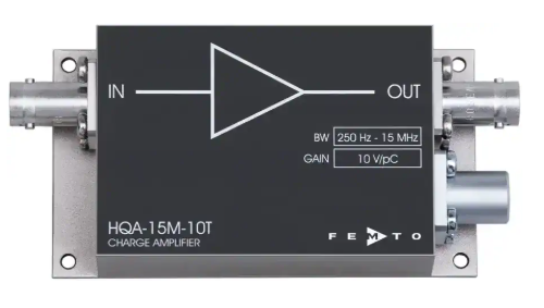
The HQA-15M-10T is a fixed-gain, high-frequency charge amplifier for engineers working with small AC charge signals. It converts signals from quartz tuning forks, piezoelectric detectors, pyroelectric detectors and longitudinal resonators into a voltage at 10 V/pC. Its frequency range extends from 250 Hz to 15 MHz, subject to the connected source capacitance, supporting resonant sensor measurements and ultrasonic vibration detection.
The AC-coupled input is designed for symmetrical, sinusoidal charge signals without an average DC component, allowing operation without a reset cycle. Input charge noise is 40 × 10⁻²¹ C/√Hz at 1 MHz with an open input, while the maximum input charge is 1 pC peak-to-peak. The compact enclosure can be installed close to the sensor to reduce input cable length and capacitance, and the amplifier does not require cooling. Typical applications include atomic force microscopy, laboratory instrumentation, resonant sensing and OEM measurement systems.
Range features
A high level overview of what this range offers
- Fixed charge gain of 10 V/pC with ±3% accuracy: Provides a defined relationship between sensor charge and output voltage.
- 250 Hz to 15 MHz frequency range: Supports resonant, ultrasonic and high-frequency charge measurements.
- 40 × 10⁻²¹ C/√Hz input charge noise at 1 MHz: Supports measurement of small charge variations with an open input.
- AC-coupled charge integration: Processes symmetrical charge signals without requiring a reset cycle.
- Recommended source capacitance below 1 nF: Helps maintain virtual-ground behaviour at the amplifier input.
- 10 V peak-to-peak output into loads of at least 100 kΩ: Provides a usable voltage signal for oscilloscopes, digitising systems and control electronics.
- Short-circuit-protected output: Adds protection during connection, testing and system integration.
- BNC signal connections and a 3-pin power socket: Simplify integration with common laboratory and measurement equipment.
- Compact 94 × 51 × 27 mm enclosure weighing 200 g: Can be positioned near the sensor to limit input cable length.
- No cooling requirement: Reduces the supporting hardware needed around the measurement front end.
Downloads
for HQA Quartz Tuning Fork Charge Amplifier
What’s in this range?
All the variants in the range and a comparison of what they offer
| Category | Parameter | Specification |
|---|---|---|
Test conditions | Standard test conditions | Supply ±15 V; ambient temperature 25 °C; output load 1 MΩ; warm-up 20 minutes, with at least 10 minutes recommended |
Gain | Charge gain | 10 V/pC at an output load of at least 100 kΩ |
Gain | Gain accuracy | ±3% |
Gain | Equivalent current gain | 1.6 V/µA at 1 MHz with a sinusoidal input and output load of at least 100 kΩ |
Frequency response | Lower cut-off frequency | 250 Hz at −3 dB |
Frequency response | Upper cut-off frequency | 15 MHz typical at −3 dB, with a maximum source capacitance of 100 pF |
Input | Input impedance | 1 GΩ in parallel with 10 nF |
Input | Effective AC input impedance | 20 Ω at 1 MHz |
Input | Input charge noise | 40 × 10⁻²¹ C/√Hz at 1 MHz with an open input; 90 × 10⁻²¹ C/√Hz at 1 MHz with 100 pF source capacitance |
Input | Equivalent input current noise | 250 fA/√Hz at 1 MHz with an open input; 570 fA/√Hz at 1 MHz with 100 pF source capacitance |
Input | Input voltage noise | 700 pV/√Hz at 1 MHz |
Input | Maximum input charge | 1 pC peak-to-peak |
Output | Output voltage range | 10 V peak-to-peak into at least 100 kΩ for linear operation; 5 V peak-to-peak into 50 Ω |
Output | Output impedance | 50 Ω; a receiving load of at least 100 kΩ is specified for the full output range |
Output | Maximum output current | 100 mA, short-circuit protected |
Output | Output noise | 1.5 mV RMS, 10 mV peak-to-peak typical with an open input; 4.6 mV RMS, 30 mV peak-to-peak typical with 100 pF source capacitance; measured with at least 1 MΩ load over 200 MHz |
Power supply | Supply voltage | ±15 V; permitted operating range ±14.5 V to ±16.5 V |
Power supply | Supply current | ±35 mA depending on operating conditions; minimum recommended supply capability ±100 mA |
Case | Dimensions | 94 × 51 × 27 mm, length × width × height |
Case | Weight | 200 g, 0.44 lb |
Case | Material | AlMg4.5Mn aluminium alloy, nickel-plated |
Temperature | Operating temperature | 0 °C to +40 °C |
Temperature | Storage temperature | −40 °C to +85 °C |
Absolute maximum ratings | Input voltage | 20 V peak-to-peak |
Absolute maximum ratings | Power-supply voltage | ±18 V |
Connectors | Input | Female BNC socket |
Connectors | Output | Female BNC socket |
Connectors | Power | Series 1S, 3-pin fixed socket; mating plug FFA.1S.303.CLAC52 |
Power connections | Pin assignment | Pin 1: +15 V; pin 2: −15 V; pin 3: ground |
Scope of delivery | Included items | HQA-15M-10T, 3-pin power connector, datasheet and transport packaging |
Ordering | Order code | HQA-15M-10T |
Accessory | Compatible power supply | PS-15-25-L; 100–240 V AC input and ±15 V DC output |
FAQs
for HQA Quartz Tuning Fork Charge Amplifier
The HQA-15M-10T is suited to sensors that produce an alternating charge and require an output proportional to that charge. A transimpedance amplifier instead produces an output proportional to current, which is the time derivative of charge. This charge-amplifier architecture integrates the input current and provides a fixed conversion of 10 V/pC across a 250 Hz to 15 MHz operating range. It is intended for sinusoidal signals from sources such as quartz tuning forks, piezoelectric detectors and longitudinal resonators. A different front end should be considered when the source produces a continuous current or an average DC component.
No, the input is intended for AC charge sources that produce no average DC background. With a symmetrical waveform, positive and negative charge alternate so that the net accumulated charge returns towards zero, removing the need for a reset mechanism. The 1 GΩ input resistance helps prevent static charge from building up, but it does not make the amplifier suitable for continuous DC current. A persistent DC component can drive the integration stage into saturation and prevent linear measurement. Engineers should therefore verify the sensor’s offset and leakage behaviour before selecting this amplifier.
The combined capacitance of the sensor and input cable should remain below 1 nF for normal operation. The typical 15 MHz upper cut-off frequency is specified with no more than 100 pF of source capacitance, so larger values can restrict the usable bandwidth. At 1 MHz, input charge noise rises from 40 × 10⁻²¹ C/√Hz with an open input to 90 × 10⁻²¹ C/√Hz at 100 pF. Equivalent input current noise also increases from 250 fA/√Hz to 570 fA/√Hz under the same conditions. Placing the amplifier close to the sensor and keeping the input cable short can therefore support lower noise and a more predictable frequency response.
With a high-impedance output load, multiply the input charge in picocoulombs by the fixed gain of 10 V/pC. For example, an input signal of 0.2 pC peak-to-peak produces a nominal output of 2 V peak-to-peak. The maximum specified input charge of 1 pC peak-to-peak corresponds nominally to the 10 V peak-to-peak linear output limit when the load is at least 100 kΩ. Gain accuracy is ±3%, so a practical design should retain additional headroom for sensor tolerances and transient peaks. A 50 Ω load limits the available output swing to 5 V peak-to-peak and should not be used where the full output range is required.
A high-impedance receiver of at least 100 kΩ is required when the full 10 V peak-to-peak output range and specified charge gain are needed. Although the amplifier has a 50 Ω output impedance, loading it with 50 Ω reduces the available output range to 5 V peak-to-peak. A 50 Ω coaxial cable can still be used while the oscilloscope, digitiser or acquisition input remains in its high-impedance mode. Cable impedance and receiver termination should therefore be treated as separate design choices. The 100 mA short-circuit capability provides protection, but it should not be treated as a normal continuous operating condition.
The amplifier requires a regulated bipolar supply of ±15 V, with an allowed operating range from ±14.5 V to ±16.5 V. Its specified current demand is ±35 mA depending on operating conditions, while a supply capable of at least ±100 mA is recommended. The 3-pin power connection assigns +15 V to pin 1, −15 V to pin 2 and ground to pin 3. A 20-minute warm-up is used for the specified test conditions, although at least 10 minutes is recommended before measurement. The ±18 V absolute maximum rating is a protection limit and must not be used as the normal supply voltage.
The quoted 40 × 10⁻²¹ C/√Hz input charge noise is a spectral-density value measured at 1 MHz with an open input, rather than a fixed minimum detectable charge. Practical resolution depends on the measurement bandwidth, source capacitance, cable behaviour and the noise introduced by the sensor and following electronics. Connecting 100 pF raises the charge-noise density to 90 × 10⁻²¹ C/√Hz and the typical output noise from 1.5 mV RMS to 4.6 mV RMS under the stated conditions. The output-noise figures use a 200 MHz measurement bandwidth and a load of at least 1 MΩ. Restricting the downstream measurement bandwidth and controlling input capacitance can support a lower integrated noise level.
The unit is specified for operation from 0 °C to +40 °C and storage from −40 °C to +85 °C. Its 94 × 51 × 27 mm enclosure weighs 200 g and uses nickel-plated AlMg4.5Mn aluminium alloy. Female BNC sockets are provided for the input and output, while power is supplied through a separate 3-pin connector. The compact case can be installed close to the charge source, which helps reduce input cable length and associated capacitance. The design must also prevent the input from exceeding 20 V peak-to-peak and keep the supply below the ±18 V absolute maximum rating.