Programmable temperature controllers
- Technology
- Photonics test and measurement
- Partner
- Stanford Research Systems (SRS)
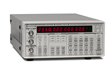
The PTC10 programmable temperature controller combines multi-channel temperature measurement, heater control and data logging in a single modular chassis. Four wide I/O slots accept optional temperature-input and heater-output cards, allowing the system to be configured around specific sensors, loads and channel counts. Depending on the installed cards, one chassis can monitor up to 16 temperature sensors and operate as many as six PID feedback loops. Available input cards support RTDs, thermistors, diodes and isolated thermocouples, while AC, unipolar DC and bipolar TEC output cards address different load characteristics.
Manual and automatic PID tuning are supported, with loop updates running at up to 50 or 60 Hz according to the mains frequency. The controller stores recent readings internally and can log longer data sets to removable USB media. A 320 × 240 touchscreen, alarms, relays, user programmes, virtual channels and USB, Ethernet or RS-232 connectivity support stand-alone operation and integration into automated test systems.
Range features
A high level overview of what this range offers
- Four-slot modular architecture: Select input and output cards for the required sensors, heaters and channel density.
- Up to 16 temperature inputs: Consolidate multi-point temperature monitoring in one controller.
- Up to six PID feedback loops: Control several thermal zones simultaneously.
- Up to 50 or 60 Hz PID rate: Deliver frequent control updates for suitably responsive thermal systems.
- Manual and automatic PID tuning: Tune loops by direct parameter entry, single-step response or relay-based methods.
- Broad sensor compatibility: Configure inputs for RTDs, thermistors, diodes or E, J, K, N and T thermocouples.
- AC, DC and bipolar TEC outputs: Match the output stage to line-powered heaters, low-noise resistive loads or thermoelectric coolers.
- One million internal readings per channel: Retain recent measurement history for on-screen plotting and remote retrieval.
- USB data logging: Extend recording capacity according to the connected storage device.
- Custom calibration tables: Use individually calibrated sensors and non-standard measurement relationships.
- 320 × 240 touchscreen: View channel values and recorded data in numeric or graphical formats.
- Channel alarms and relay outputs: Monitor upper, lower and rate-of-change limits and configure automated responses.
- User programmes and virtual channels: Implement sequencing, calculated channels, cascade control and automated actions.
- USB, Ethernet and RS-232 connectivity: Integrate the controller with computers and automated test equipment, with optional GPIB available.
What’s in this range?
All the variants in the range and a comparison of what they offer
| Category | Specification | Value |
|---|---|---|
Controller | Architecture | Modular chassis with four wide slots for optional temperature-input or heater-output cards; standard analogue and digital I/O use two narrow slots |
Controller | Maximum temperature inputs | Up to 16, depending on installed cards |
Controller | Maximum heater outputs and PID loops | Up to 6 |
Controller | Input conversion | Individual 24-bit ADC for each temperature-input channel |
Controller | Maximum PID rate | 50 or 60 Hz, depending on mains frequency |
Controller | PID tuning | Manual tuning; single-step and relay-based automatic tuning |
Controller | Display | 320 × 240-pixel touchscreen with numeric and graphical displays |
Controller | Display resolution | 0.001 °C, °F, K, V, A, W or related units between –1000 and 1000; six significant figures otherwise |
Controller | Data-logging rate | 10 samples per second per channel to 1 sample per hour per channel |
Controller | Internal log | Most recent 1,000,000 readings from each channel |
Controller | Custom calibration tables | Minimum 2 points; maximum file length 16,384 characters, equivalent to approximately 400–800 points |
Controller | User programmes | Up to 10 can run concurrently |
Controller | Virtual channels | 3 |
Standard analogue I/O | Channels and range | 4 channels independently configurable as inputs or outputs; ±10 V |
Standard analogue I/O | Resolution | 24-bit input; 16-bit output |
Standard analogue I/O | ADC noise | 30 µV RMS or 100 µV peak-to-peak at 10 samples per second |
Standard analogue I/O | Maximum output current | 10 mA; an external amplifier is required for direct heater control |
Standard digital I/O | Lines | 8 optoisolated TTL lines, configurable as eight inputs or eight outputs |
Relays | Outputs and contact rating | 4 independent SPDT relays; 5 A maximum and 250 VAC maximum |
Communications | Interfaces | USB, Ethernet and RS-232 standard; optional GPIB compliant with IEEE 488.2 |
Electrical | Input power | 10 A; 88–132 VAC or 176–264 VAC; 47–63 Hz or DC |
Mechanical | Dimensions | 17 in wide × 5 in high × 18 in deep |
Mechanical | Weight | 25 lb |
Memory | Volatile memory | 512 MB SDRAM used as operating memory and cleared when power is switched off |
Memory | Non-volatile memory | 32 MB flash memory for firmware and user settings |
PTC320 input card | Inputs and measurement range | One 2-wire or 4-wire thermistor, diode or RTD input; approximately 1 Ω to 2.5 MΩ resistance measurement |
PTC320 input card | Diode measurement | 0–2.5 V input; 10 µA excitation; initial accuracy of 10 µV plus 0.01% of reading; 1.5 µV RMS noise |
PTC321 input card | Inputs and range | Four 4-wire inputs for 100 Ω platinum RTDs; 0–400 Ω and –215 °C to 850 °C with IEC 751 Pt100 sensors |
PTC321 input card | Accuracy and noise | ±30 mK initial accuracy; 2 mK RMS noise at 25 °C and 10 samples per second |
PTC321 input card | Drift | 1.4 mK/°C ambient; ±15 mK/year at 25 °C ambient |
PTC323 input card | Inputs and resistance measurement | Two 4-wire thermistor, diode or RTD inputs; approximately 1 Ω to 2.5 MΩ |
PTC323 input card | Diode measurement | 0–2.5 V input; 10 µA excitation; initial accuracy of 10 µV plus 0.01% of reading; 3 µV RMS noise |
PTC330 input card | Inputs and thermocouple types | Four optoisolated inputs for E, J, K, N or T thermocouples; each card is configured for one type |
PTC330 input card | Temperature ranges | Type E: –270 °C to 980 °C; J: –210 °C to 1177 °C; K: –270 °C to 1342 °C; N: –270 °C to 1281 °C; T: –270 °C to 383 °C |
PTC330 input card | Accuracy, noise and isolation | ±500 mK over 12 months; 20 mK RMS at 10 samples per second; 100 dB CMRR and 250 VAC isolation |
PTC420 output card | Output | Solid-state-relay line-voltage output rated for 120/240 VAC and 5 A maximum |
PTC420 output card | Cycle and resolution | Adjustable 1–240 second cycle; 0.1% resolution with a 10-second cycle |
PTC420 output card | Minimum heater resistance | 24 Ω at 110 VAC; 46 Ω at 230 VAC |
PTC430 output card | Output | Linear unipolar DC current source rated at 50 W |
PTC430 output card | Output ranges | 50 V/1 A, 20 V/2 A, 50 V/0.5 A, 20 V/0.5 A, 50 V/0.1 A or 20 V/0.1 A |
PTC430 output card | Resolution and accuracy | 24-bit with dithering or 16-bit without dithering; accuracy from ±1 mA to ±0.01 mA according to range |
PTC431 output card | Output | Unipolar DC current source rated at 100 W |
PTC431 output card | Ranges and resolution | 20 V or 50 V with 2 A, 0.6 A or 0.2 A ranges; 16-bit resolution |
PTC440 output card | TEC output | Linear bipolar DC current source from –5 A to +5 A; 50 W maximum; 12 V compliance at zero output current |
PTC440 output card | Resolution and accuracy | 0.15 mA resolution; ±5 mA accuracy |
PTC440 output card | Sensor input | One 2-wire or 4-wire thermistor, RTD or IC temperature-sensor input |
PTC440 output card | Sensor ranges and excitation | 1 Ω to 250 kΩ, 0–2.5 V or 0–1 mA; 10 µA, 100 µA or 1 mA excitation |
FAQs
for Programmable temperature controllers
Select the input card according to the sensor type, required channel density and acceptable measurement uncertainty. The PTC320 handles one 2-wire or 4-wire RTD, thermistor or diode and covers resistances from approximately 1 Ω to 2.5 MΩ, making it suitable where one broadly configurable channel is needed. For four Pt100 channels, the PTC321 provides dedicated 4-wire inputs, a –215 °C to 850 °C range, ±30 mK initial accuracy and 2 mK RMS noise at 10 samples per second. The PTC323 provides two flexible resistive or diode inputs, while the PTC330 provides four isolated E, J, K, N or T thermocouple inputs. Dedicated cards generally suit higher channel density, while multi-sensor cards provide greater configuration flexibility.
The output card should be matched to the heater voltage, required power, load polarity and thermal response time. The PTC420 switches 120 or 240 VAC at up to 5 A and uses an adjustable 1–240 second cycle, so it is intended for relatively slow line-powered heaters. The PTC430 supplies up to 50 W with 20 V and 50 V ranges, while the PTC431 supplies up to 100 W and offers 2 A, 0.6 A and 0.2 A current ranges. The PTC440 provides a bipolar –5 A to +5 A output for heating and cooling with thermoelectric devices. For stable control, the selected range should provide adequate headroom without being unnecessarily large for the connected load.
The chassis can monitor up to 16 temperature sensors and operate up to six PID feedback loops, although the actual combination depends on the installed cards. Four wide slots accept sensor-input or heater-output cards, while the standard analogue and digital cards occupy two narrow slots. The four ±10 V analogue channels can act as PID inputs or outputs, but their 10 mA output limit means that an external amplifier is required for heater drive. Up to four PTC431 cards can be installed, but only two can run at full power simultaneously. Channel count, load power and simultaneous operating conditions should therefore be mapped before the card configuration is finalised.
The acquisition rate determines how frequently measurements are taken and PID outputs are updated, while the logging rate determines how often values are stored. Feedback loops can operate at up to 50 or 60 Hz, whereas logging can be set between 10 points per second and one point per hour for each channel. Internal memory retains the latest one million readings per channel, covering about 1.2 days at a 0.1-second interval or approximately two years at a one-minute interval. USB logging can extend the recording period according to the available storage capacity. In practice, select the acquisition rate for the thermal dynamics of the system and the logging interval for the required time resolution and file size.
A custom calibration table should be used when the built-in curve does not match the individual sensor or when a non-standard transducer is connected. Each input channel can have its own table, loaded through a USB storage device or remote command. The file must contain at least two monotonic calibration points and may contain up to 16,384 characters, which is typically around 400–800 points. RTD calibration points should normally be spaced no more than 10 °C apart, while thermistor points should be spaced by 1 °C or less for finer interpolation. The table should extend beyond the intended operating range because an out-of-range reading blanks the channel and freezes any PID loop using it.
Each input can be assigned upper, lower and rate-of-change limits, allowing the controller to respond to excessive temperature, rapid drift or a missing sensor. A triggered alarm can produce an audible indication, activate a selected relay and set a chosen output channel to zero. The digital I/O card provides four SPDT relays rated at up to 5 A and 250 VAC, together with eight optoisolated TTL lines for external status or control signals. Alarm-driven relay operation requires the digital I/O card to be installed in slot 6. These functions can support equipment protection and automated shutdown logic, but hazardous heating systems should still use an independently engineered protective circuit and power-disconnection method.
USB, Ethernet and RS-232 are included, and an IEEE 488.2 GPIB interface can be added when compatibility with existing instrumentation is required. All controller functions can be read or controlled through these interfaces, while the USB connection appears as a serial COM port on the host computer. The macro language supports variables, loops, conditional statements and subroutine calls, with up to ten programmes running concurrently. Three virtual channels can hold calculated values, follow other channels or participate in cascade-control arrangements. Together with the analogue channels, isolated TTL lines and relays, these facilities can support supervisory control without requiring the host computer to handle every local action.
Switching off the power clears the 512 MB SDRAM used as operating memory, but it does not erase all stored information. A 32 MB flash memory retains the firmware and user settings, while the internal clock continues to retain its date and time. Removable USB media may also contain user programmes, sensor calibration curves and log files. Clearing non-volatile contents requires the relevant I/O cards to be installed, a full factory reset to be performed and the firmware to be reflashed; removable media should be taken out and reformatted separately. This distinction is important in secure facilities because removing mains power alone does not clear retained configuration data or files stored on USB media.