Laser autofocus systems
- Technology
- Photonics accessories
- Partner
- Prior Scientific
Laser autofocus systems provide closed-loop focus control for compatible microscopy, inspection and imaging applications. This product range is presented as a category overview because individual models, part numbers and validated performance values are not currently available. Selection depends on the optical path, sample interface, objective set, Z-axis actuator and control architecture.
Laser wavelength, safety classification, capture range, correction rate, focus accuracy and actuator compatibility must be confirmed for the intended configuration. Mechanical mounting, electrical connections, communications and environmental limits also require model-specific verification. Engineers should review the applicable optical drawings, compatibility statements and installation documents before approving a system design.
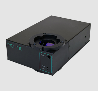
Range features
A high level overview of what this range offers
- Laser autofocus technology: Can support closed-loop focus maintenance when the optical path, sample and actuator are compatible.
- Imaging-system integration: May support automated microscopy or inspection applications, depending on the selected model.
- Application-based configuration: Allows optical, mechanical and motion-control requirements to be considered together during selection.
- Range-level product category: Provides a basis for evaluating autofocus configurations once variant data becomes available.
- Model-dependent operation: Encourages verification of performance, safety and compatibility before the design is approved.
FAQs
for Laser autofocus systems
Confirm the microscope’s optical architecture, available insertion point, working distance, objective set, sample interfaces and Z-axis actuator before selecting a model. Autofocus performance depends on whether the projected beam and its return can pass through the optical path without being blocked or distorted. Objective magnification, numerical aperture, immersion medium and tube-lens arrangement can alter capture range and signal quality. The mechanical envelope, flange arrangement and cable routing must also fit without restricting turrets, filter cubes or illumination paths. Integration should not proceed until a model-specific optical drawing and compatibility statement have been checked against the complete microscope configuration.
Laser wavelength is a system-level compatibility decision rather than an isolated sensor specification. It must be compared with the transmission characteristics of dichroics, emission filters, detectors, fluorophores, Raman excitation bands and optical coatings in the return path. A wavelength that is blocked or detected by the imaging channel can weaken the focus signal or introduce unwanted background. Output power and laser class must also be evaluated alongside the wavelength. Because no wavelength or power values are verified for this range, engineers should obtain spectral transmission data and the applicable laser safety classification before selection.
The selected system should have a capture range that exceeds the expected Z-axis error, a correction rate suited to the motion profile and an accuracy comfortably below the application’s permissible focus deviation. A wide capture range without sufficient update speed may be unsuitable for rapid scanning, while a fast loop with incorrect actuator tuning may become unstable. Accuracy should be assessed relative to objective numerical aperture and depth of field rather than as an isolated figure. Performance data should be requested for each objective and actuator combination. With no validated figures available, suitable design margins and acceptance tests should be defined before procurement.
Suitability depends on whether the sample, substrate or nearby reference interface returns a stable and separable laser signal. Reflective industrial samples may behave differently from glass slides, liquid chambers or multilayer biological vessels, particularly where several interfaces produce competing reflections. Surface tilt, roughness, coatings, contamination and changes in refractive index can shift or weaken the detected signal. Engineers should establish which interface will be tracked and whether the imaging plane must remain offset from that reference. Practical evaluation should use representative samples covering the full expected process range rather than a single clean specimen.
Confirm that the autofocus output can command the intended Z-axis mechanism directly or through a compatible controller. Stepper motors, servo stages, piezo objective positioners and piezo sample stages differ in travel, bandwidth, resolution, load capacity and command interface. The control loop also needs suitable travel limits, direction conventions and fail-safe behavior when the focus signal is lost. Electrical details such as analog range, pulse-and-direction levels, connectors and grounding must match at both ends. No actuator interface is verified for this range, so the complete sensor, controller and mechanism chain should be reviewed as one closed-loop system.
Multi-objective operation requires objective-specific calibration and a reliable way to recall the correct parameters after each turret change. Differences in magnification and numerical aperture affect depth of field, reflected signal strength and the Z correction needed to maintain focus. Immersion media and coverslip geometry can introduce further optical interfaces that require separate setup. Engineers should confirm how many objective profiles can be stored, how profile selection is triggered and whether parfocal offsets are handled automatically. If these functions are unavailable or undocumented, changing objectives may require manual recalibration and could interrupt an automated imaging sequence.
Before installation, obtain the model’s laser class, wavelength, maximum accessible emission, labeling requirements, interlock provisions and intended-use statement. Laser class alone is not sufficient because the completed optical assembly may change how radiation is enclosed or accessed during alignment and servicing. Electrical safety, electromagnetic compatibility and applicable environmental declarations should also be checked for the final configuration. Operating procedures must address alignment, protective covers, fault conditions and authorized maintenance. Because no classifications or approvals are verified here, compliance should remain an open design requirement rather than an assumed product property.
Commissioning should use predefined acceptance tests that reproduce the actual imaging workflow. Test focus acquisition after known Z offsets, continuous correction during stage motion, recovery after signal loss, behavior at travel limits and stability over the required operating period. Repeat these tests with every objective, sample type, illumination mode and actuator configuration approved for use. Pass criteria should be expressed in application terms, including permissible focus error, maximum recovery time and acceptable failure rate, rather than relying solely on nominal specifications. Model-specific limits remain unverified, so the acceptance protocol should be agreed before purchase and retained for subsequent maintenance checks.