SR1 Dual domain audio analyser
- Technology
- Analysers
- Partner
- Stanford Research Systems (SRS)
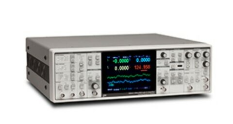
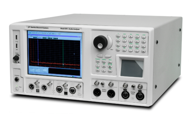
The SR1 dual-domain audio analyser is designed for the development, verification and production testing of audio electronics and electroacoustic systems. Its generator and analyser functions operate across analogue and digital domains, allowing one platform to evaluate amplifiers, converters, filters, processors, interfaces and loudspeaker-related signal chains. Two analysers can run simultaneously on either analogue or digital inputs, supporting correlated measurements and cross-domain workflows. Available functions include time-domain, single- and dual-channel FFT, THD, IMD, histogram, multitone and jitter analysis.
Balanced XLR, unbalanced BNC and optical connections accommodate AES/EBU, S/PDIF-EIAJ and Toslink signals at sample rates from 24 kHz to 216 kHz. Integrated controls, saved configurations, QuickMeas routines and remote programming interfaces support manual bench work and automated test sequences. An optional 80 MHz digitiser extends digital carrier analysis with time records, spectra, histograms and eye diagrams.
Range features
A high level overview of what this range offers
- Symmetrical analogue and digital analysis: Assign the same analyser functions to either signal domain.
- Two simultaneous analysers: Perform correlated measurements and dual-channel test configurations.
- 200 kHz analogue measurement range: Cover conventional audio-band and extended-bandwidth testing.
- Residual analogue THD+N down to −112 dB: Evaluate low-distortion audio circuits under the stated level and bandwidth conditions.
- Dual-channel FFT analysis: Measure frequency response, coherence, impulse response, group delay and energy-time behaviour.
- Multiple generator waveforms: Generate sine, chirp, noise, multitone, MLS, IMD, burst and arbitrary signals.
- Digital audio sample rates from 24 kHz to 216 kHz: Test professional, consumer and optical digital audio interfaces.
- Programmable carrier impairments: Apply jitter, rise-time, common-mode, normal-mode and cable-simulation disturbances.
- Up to 50 independently adjustable tones: Make single-shot multitone measurements of level, distortion, noise and crosstalk.
- GPIB, RS-232, Ethernet and COM control: Integrate the analyser into automated test systems.
- On-board scripting and learning mode: Create repeatable test routines without requiring an external computer for every sequence.
- Optional 80 MHz digitiser: Add eye diagrams, carrier time records, probability histograms and spectral measurements.
Downloads
for SR1 Dual domain audio analyser
What’s in this range?
All the variants in the range and a comparison of what they offer
| Section | Specification | Value |
|---|---|---|
Analogue signal generator | Amplitude range, RMS | 1 µV to 28.3 V balanced; 1 µV to 14.1 V unbalanced |
Analogue signal generator | Amplitude accuracy | ±0.5% or ±0.043 dB at 1 kHz |
Analogue signal generator | Frequency range | 10 Hz to 200 kHz with high-bandwidth DAC |
Analogue signal generator | Frequency accuracy | ±0.0005% or 5 ppm |
Analogue signal generator | Output configurations | Balanced ground, balanced float, unbalanced ground, unbalanced float and common-mode test |
Analogue signal generator | Source impedance | 50 Ω, 150 Ω or 600 Ω balanced; 25 Ω, 75 Ω or 600 Ω unbalanced |
Analogue signal generator | Maximum power into 600 Ω | 30.5 dBm balanced; 24.9 dBm unbalanced |
Analogue signal generator | Output crosstalk | −125 dB from 10 Hz to 20 kHz; −100 dB above 20 kHz |
Low-distortion sine | Flatness relative to 1 kHz | ±0.020 dB from 20 Hz to 20 kHz; ±0.025 dB from 10 Hz to 64 kHz; ±0.05 dB from 10 Hz to 200 kHz |
Low-distortion sine | Residual THD+N at 1 kHz and 4 Vrms | −112 dB typical with 22 kHz bandwidth |
Low-distortion sine | Residual THD+N from 20 Hz to 20 kHz | −106 dB + 1 µV at 22 kHz bandwidth; −100.5 dB + 1.7 µV at 80 kHz; −97 dB + 2.5 µV at 200 kHz |
Analogue waveforms | Phased sines | 0° to 360° range with 0.001° resolution |
Analogue waveforms | IMD formats | SMPTE/DIN, CCIF/DFD and DIM/TIM |
Analogue waveforms | Noise | White, pink, filtered white or pink and USASI |
Analogue waveforms | Multitone | 1 to 50 tones |
Analogue waveforms | MLS | Repetition rates from 2^8 to 2^20 |
Analogue waveforms | Square wave | 10 Hz to 50 kHz |
Analogue waveforms | Arbitrary waveform | 256 to 136k samples |
Analogue waveforms | Constant offset | DC to 20 Vp unbalanced or 40 Vp balanced |
Digital audio generator | Balanced output range | 16 mV to 10.2 V into 110 Ω |
Digital audio generator | Unbalanced output range | 4 mV to 2.55 V into 75 Ω |
Digital audio generator | Output formats | Balanced XLR AES/EBU, dual-connector XLR, unbalanced BNC S/PDIF-EIAJ, dual-connector BNC and optical Toslink |
Digital audio generator | Output sample rate | 24 kHz to 216 kHz |
Digital audio generator | Sample-rate accuracy | ±5 ppm |
Digital audio generator | Output impedance | 110 Ω balanced; 75 Ω unbalanced |
Digital sine | Frequency range | 10 Hz to Fs/2 |
Digital sine | Flatness | ±0.001 dB |
Digital sine | Harmonic and spurious content | −148 dB |
Digital waveforms | Digital test signals | Digital constant, count, rotating bits, staircase and J-test |
Digital waveforms | Dither | None, triangular or rectangular probability distribution |
Digital carrier impairments | Jitter waveforms | Sine, square, uniform noise, band-pass filtered noise and chirp |
Digital carrier impairments | Jitter frequency and amplitude | 2 Hz to 200 kHz; 0 UI to 13 UI |
Digital carrier impairments | Normal-mode noise | 0 to 637 mVpp unbalanced; 0 to 2.55 Vpp balanced |
Digital carrier impairments | Common-mode sine | 0 to 20 Vpp and 10 Hz to 100 kHz, balanced only |
Digital carrier impairments | Cable simulation | Simulates 100 m of digital audio cable |
Digital carrier impairments | Variable rise time | 5 ns to 400 ns |
Analogue inputs | RMS input range | 62.5 mV to 160 V |
Analogue inputs | Input configurations | XLR, BNC, generator monitor and digital-audio common mode |
Analogue inputs | Input impedance | 200 kΩ and 95 pF balanced; 100 kΩ and 185 pF unbalanced |
Analogue inputs | Input crosstalk | ≤−140 dB from 10 Hz to 50 kHz; ≤−135 dB above 50 kHz |
High-bandwidth ADC | Converter and sampling rate | 16-bit sigma-delta; 512 kHz |
High-bandwidth ADC | Frequency range | DC to 228 kHz |
High-resolution ADC | Converter and sampling rate | 24-bit sigma-delta; 64 kHz or 128 kHz fixed, or 24 kHz to 216 kHz adjustable |
High-resolution ADC | Frequency range | DC to 0.45 Fs |
Digital inputs | Input formats | Balanced XLR AES/EBU, dual-connector XLR, unbalanced BNC S/PDIF-EIAJ, dual-connector BNC and optical Toslink |
Digital inputs | Input sample rate | 24 kHz to 216 kHz |
Digital inputs | Input impedance | High impedance or 110 Ω balanced; high impedance or 75 Ω unbalanced |
Analogue RMS level meter | Accuracy at 1 kHz | ±0.5% or ±0.043 dB |
Analogue frequency meter | Range and accuracy | 8 Hz to 300 kHz; timebase error ±2 ppm + 10 mHz |
Digital frequency meter | Range and accuracy | 10 Hz to 0.45 Fs; ±100 ppm |
Digital phase meter | Accuracy | ±0.05° at frequencies of at least 50 Hz |
High-resolution ADC | Residual noise | <−117.5 dBu from 22 Hz to 22 kHz; <−115 dBu from 22 kHz to 57.6 kHz; <−120 dBu A-weighted |
High-bandwidth ADC | Residual noise | <−118 dBu from 22 Hz to 22 kHz; <−113 dBu to 80 kHz; <−110 dBu to 200 kHz; <−120 dBu A-weighted |
High-bandwidth ADC | Residual THD+N | −112 dB typical at 1 kHz, 4 Vrms and 22 kHz bandwidth; −98 dB + 2.5 µV at 200 kHz bandwidth |
Time-domain analyser, digital | Amplitude accuracy and flatness | ±0.001 dB at 1 kHz; ±0.001 dB from 15 Hz to 22 kHz |
Time-domain analyser, digital | Residual THD+N | −140 dBFS |
Filters | Low-pass | Fourth-order Butterworth adjustable from Fs/40 to 0.45 Fs; fixed 20 kHz, 40 kHz and 80 kHz elliptical filters to AES17 |
Filters | Band-pass response | High-bandwidth ADC: 1/3-octave Class II, four-pole; high-resolution ADC: 1/3, 1/6, 1/12 and 1/24-octave Class III, six-pole |
Filters | Weighting and detector responses | A-weighting, C-message, CCITT, CCIR weighted, unweighted or 2 kHz normalised; RMS, peak and quasi-peak CCIR-468 |
FFT analysers | Channels and frequency range | Single- and dual-channel; DC to 200 kHz with high-bandwidth ADC or DC to 0.45 Fs with high-resolution ADC |
FFT analysers | Number of lines and zoom | 256 to 32k lines; span narrowing up to 512× |
Dual-channel FFT | Measurements | Frequency response, impulse response, quasi-anechoic response, coherence, energy-time curve and group delay |
THD analyser | Harmonic analysis | Two independent sets of user-selectable harmonics from 2× to 14× |
IMD analyser | Measurement formats | SMPTE/DIN, CCIF/DFD and DIM/TIM |
Multitone analyser | Measurements | Level, frequency response, THD+N, THD, noise, IMD and crosstalk |
Digital carrier measurements | Sample-rate range and accuracy | 24 kHz to 216 kHz; ±5 ppm |
Digital carrier measurements | Output-to-input delay | −12.7 UI to +115.1 UI with 60 ns resolution |
Jitter analyser | Residual jitter | ≤600 ps from 50 Hz to 100 kHz |
Timebase | Internal accuracy and synchronisation | 5 ppm; external clock, AES11 reference or NTSC, PAL and SECAM video reference |
Timebase | Optional rubidium reference | ±5 × 10^−11 accuracy at shipment; ageing below 5 ppb over 20 years |
Optional digitiser, option 01 | Sampling rate and acquisition length | 80 MHz; 4k, 8k, 16k, 128k, 256k, 512k, 1M or 2M samples |
Optional digitiser, option 01 | Measurements | Input and jitter time records, input and jitter spectra, pulse-width and pulse-rate histograms, jitter probability histogram and eye diagrams |
General | Computer interfaces | GPIB, RS-232, Ethernet and COM |
General | Power | <250 W; 90 VAC to 264 VAC; 47 Hz to 63 Hz |
General | Dimensions | 17 in × 8.5 in × 20.25 in, width × height × depth |
General | Weight | 40 lb |
General | Warranty | One year covering parts and labour for defects in materials and workmanship |
Fs denotes sampling frequency, and BW denotes measurement bandwidth.
FAQs
for SR1 Dual domain audio analyser
Yes. Its high-resolution converter path can operate at fixed 64 kHz or 128 kHz rates, or adjust from 24 kHz to 216 kHz, allowing it to synchronise with digital input or output rates during analogue-to-digital and digital-to-analogue testing. The time-domain, FFT, THD, IMD, histogram and multitone functions can be assigned to either domain, and two analysers can operate simultaneously. This arrangement is useful when comparing input and output level, phase, frequency response or distortion through a mixed-signal chain. The selected converter bandwidth and sample rate should be matched to the device under test so that filtering and bandwidth limits do not obscure the result.
Use the high-bandwidth converter when the measurement must extend towards 200 kHz or when out-of-band behaviour is important. It is a 16-bit sigma-delta path sampling at 512 kHz, with an input frequency range extending to 228 kHz and FFT analysis specified to 200 kHz. The 24-bit high-resolution path is more appropriate for lower-noise measurements and can operate at fixed or adjustable sample rates, with bandwidth limited to 0.45 Fs. For example, at Fs 128 kHz its A-weighted residual noise is below −120 dBu. The correct choice therefore depends on whether bandwidth or low-level resolution is the primary measurement requirement.
The instrument can measure low-distortion audio circuits, but its own residual floor must remain below the expected output from the device under test. At 1 kHz, 4 Vrms and a 22 kHz bandwidth, the analogue generator reaches a typical residual THD+N of −112 dB, while the high-bandwidth analyser is also specified at −112 dB under comparable conditions. Residual noise reaches below −118 dBu over 22 Hz to 22 kHz, with A-weighted results below −120 dBu. Wider bandwidths increase the stated residual noise and THD+N contribution. Engineers should therefore document generator level, input range, converter path, weighting and measurement bandwidth with every result.
The digital input and output system supports balanced XLR AES/EBU, unbalanced BNC S/PDIF-EIAJ, dual-connector XLR and BNC formats, and optical Toslink. Input and output sample rates span 24 kHz to 216 kHz, with a stated sample-rate accuracy of ±5 ppm. Balanced electrical outputs are adjustable from 16 mV to 10.2 V into 110 Ω, while unbalanced outputs range from 4 mV to 2.55 V into 75 Ω. High-impedance input modes are also available when termination is not required. This coverage allows interface amplitude, format, status, sample-rate and carrier behaviour to be checked across professional and consumer digital-audio equipment.
The standard jitter analyser measures jitter in both time and frequency domains, with residual jitter specified at no more than 600 ps from 50 Hz to 100 kHz. Generated impairments include sine, square, uniform-noise, band-pass-noise and chirp jitter from 2 Hz to 200 kHz, with amplitudes up to 13 UI. The carrier can also be subjected to normal-mode noise, balanced common-mode sine signals up to 20 Vpp, variable rise times from 5 ns to 400 ns and a 100 m cable simulation. These controls support receiver-tolerance and interface-robustness testing. For detailed waveform, histogram and eye-diagram analysis, the optional 80 MHz digitiser is required.
Yes, particularly when the dual-channel FFT analyser is combined with FFT, log-sine or variable-speed chirp signals. The analyser provides up to 32k FFT lines, 512× zoom and measurements including impulse response, frequency response, coherence, quasi-anechoic response, energy-time curve and group delay. Log-sine chirps can separate harmonic responses in time, allowing the linear response and individual distortion orders to be gated and examined separately. Under documented pink-spectrum test conditions, log-sine and variable-speed chirps produced crest factors around 4 to 5 dB, approximately 6 to 8 dB below pink-filtered MLS. In practice, time-window length and the arrival time of reflections will determine the lowest reliable frequency in a gated acoustic result.
Yes. Remote control is available through GPIB, RS-232 and Ethernet using VXI-11 commands, while the COM interface supports control from compatible Windows applications. On-board scripts can be written in VBScript, JScript or Python, and learning mode can record user operations before converting them into an editable script. Saved configurations, sweeps and QuickMeas routines can also be used to standardise recurring procedures. The integrated control computer uses Windows XP Embedded, so network compatibility, access controls and long-term software support should be reviewed before deployment. For production use, test limits, settling criteria, error handling and result storage should be defined as part of the automation design.
The enclosure measures 17 in wide, 8.5 in high and 20.25 in deep, and the instrument weighs 40 lb. Additional clearance is needed behind the unit for signal connectors, the mains lead, communications cables and ventilation. Power consumption is below 250 W, with operation specified from 90 VAC to 264 VAC at 47 Hz to 63 Hz. The line-voltage selector and fuse arrangement should be checked against the local supply before power is applied. Its depth and weight mean that a rack installation should use suitable support rails or a shelf rather than relying only on the front-panel fixings.