High voltage pulse transformers
- Technology
- Photonics accessories
- Partner
- Pearson Electronics
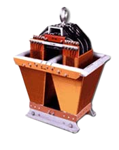
These custom high-voltage pulse transformers are intended for pulsed-power systems that require short, high-amplitude output pulses. The range covers output voltages from 100 to 500 kV and pulse lengths from 0.25 to 50 µs, while load impedance, capacitance, pulse shape and repetition rate are defined for each project. As a custom-engineered range rather than a fixed catalogue model, it has no universal part number or single standard configuration. The open construction allows the transformer assembly to operate within a suitable insulating-oil tank.
The design minimises solid insulation in regions exposed to high electric fields and places the intended weakest region between the high-voltage corona ring and the core. Engineers can specify monofilar or bifilar secondary windings, voltage ratio, polarity, insulation requirements and selected accessories. The range is intended for pulse modulators and line-type pulser systems where transformer behaviour must be matched to the source, load and protection circuitry.
Range features
A high level overview of what this range offers
- Custom electrical configuration – Matches the voltage ratio, impedance, load capacitance and pulse shape to the intended circuit.
- 100–500 kV pulse output range – Covers a defined range of high-voltage pulsed-power duties.
- 0.25–50 µs pulse lengths – Accommodates short and extended pulse profiles within the documented range.
- Open construction for oil immersion – Uses the surrounding high-voltage insulating oil as part of the dielectric system.
- Minimal solid insulation in high-field regions – Helps limit the exposure of solid winding insulation to flashover stress.
- Defined flashover region – Places the intentional weakest region between the high-voltage corona ring and the core.
- Typical 50–100% voltage stand-off safety factor – Provides operating margin while retaining the need for suitable overvoltage protection.
- Vacuum oil-impregnated core – Reduces trapped air that could form bubbles as the core warms.
- Monofilar or bifilar secondary configurations – Supports different secondary circuit and heater-current requirements.
- Configurable system accessories – Allows a filament transformer, current monitor or voltage divider to be considered during specification.
What’s in this range?
All the variants in the range and a comparison of what they offer
| Specification | Range or configuration |
|---|---|
Product type | Custom high-voltage pulse transformer range |
Pulse output voltage | 100–500 kV |
Pulse length | 0.25–50 µs |
Construction | Open construction |
Operating dielectric | High-voltage insulating oil |
Solid insulation approach | Minimum solid insulation in regions of high electric field |
Typical voltage stand-off safety factor | 50–100% |
Intentional weakest region | Between the high-voltage corona ring and the core |
Core preparation | Oil impregnated under vacuum |
Recommended oil breakdown test | At least 30 kV RMS using a standard 60 Hz oil test cup with 0.1-inch electrode spacing |
Rise-time definition | Measured from 10% to 90% voltage amplitude, assuming a step-function resistive source |
Impedance configuration | Matched source and load impedance, or a specified primary source impedance |
Primary and secondary polarity | Same, opposite or interchangeable |
Secondary low-end insulation | AC, DC or pulse insulation to the core and baseplate, or none |
Primary low-end insulation | AC, DC or pulse insulation to the core and baseplate, or none |
Secondary winding | Monofilar or bifilar |
Accessory options | Filament transformer for bifilar configurations, current monitor and voltage divider |
FAQs
for High voltage pulse transformers
Start by defining the operating pulse output voltage, load resistance at that voltage and the load capacitance measured in its actual dielectric and surroundings. Then provide the required flat-top length, rise time from 10% to 90%, overshoot, droop and repetition rate, together with the pulse voltage and duration at that rate. The primary-to-secondary ratio, source impedance or matched impedance condition, and required polarity relationship must also be settled. Insulation requirements at both low ends relative to the core and baseplate, plus the choice of monofilar or bifilar secondary, complete the electrical definition. These values allow the magnetic and insulation design to be matched to the real circuit rather than treating the 100–500 kV range as a fixed configuration.
The open-construction transformer is intended to operate in high-voltage insulating oil, so the oil forms part of the insulation system rather than serving only as a cooling medium. It should achieve at least 30 kV RMS breakdown in a standard 60 Hz oil test cup with 0.1-inch electrode spacing, and repeated samples should be assessed using the lowest result. Dirt, free air bubbles and water can reduce dielectric strength and initiate flashover or tracking. In practice, the tank and components should be cleaned before filling, followed by oil filtration after installation and after any sparkover. Filling methods should minimise aeration, and the tank should be sealed once operation is stable.
First confirm that the required output lies between 100 and 500 kV and that the pulse duration falls within 0.25 to 50 µs. Those two values do not establish suitability on their own because load resistance, load capacitance, rise time, overshoot, flat-top droop and repetition rate all affect transformer design. A capacitive load changes the energy and rise-time requirements, while repetition rate influences average heating even when peak voltage remains unchanged. The source impedance and primary-to-secondary ratio must also be considered as part of the pulse-forming network. Selection should therefore use the complete operating waveform and the load characteristics measured in the intended dielectric environment.
Use layered protection that detects abnormal charging behaviour before repeated pulses can stress the transformer. A fast overvoltage sensing circuit can inhibit the next and subsequent switch triggers when charging voltage exceeds a preset threshold; a waveform-faithful voltage divider, PFN bleeder resistance and simultaneous power-supply shutdown are relevant parts of this approach. A primary spark gap with series resistance or a thyrite element may provide additional clamping, but these are secondary measures rather than substitutes for fault detection. The pulse switch must also have suitable voltage hold-off, and protection should respond to continuous conduction. This matters because some modulator faults can charge the filter capacitor to more than twice the normal supply value.
Load mismatch can change the actual secondary voltage even when the charging voltage appears correct. A load resistance that is higher than intended can allow the transformer output voltage to rise, while very low resistance combined with incomplete PFN reverse-charge removal can produce successive charging-voltage build-up. Resistance should therefore be verified at full operating voltage using suitable voltage and pulse-current measurements rather than inferred from low-voltage or static data. Temperature-dependent dummy loads also need attention because their resistance can move during operation. For design selection, provide the operating load resistance, measured capacitance and either the matched source/load impedance or the actual primary source impedance.
The choice depends on the secondary circuit and whether a paired winding is required to carry heater current. A bifilar design requires the expected current through the windings and the voltage between them to be stated, whereas a monofilar winding avoids this additional inter-winding duty. If a bifilar winding carrying heater current flashes over between its two legs, the heater supply can feed a heavy follow-on arc even though the pulse circuit alone would not normally damage the winding. Suitable fusing or circuit-breaker protection is therefore necessary in the heater circuit. Where bifilar operation is required, the associated filament-transformer requirement should be defined alongside pulse voltage, insulation and polarity.
Continuous filtration is not automatically required in a stable system with clean oil, a sealed tank, no overvoltage events and no undetected corona from sharp high-voltage points. Initial filtration remains important because dust, lint or chips introduced during assembly can drift into high-field regions and cause delayed sparkover. Filtration should also follow any flashover because carbon contamination reduces oil strength and can contribute to tracking on solid insulation. If cleanliness, sealing or fault-free operation cannot be assured, continuous filtration can reduce the risk of contamination-related downtime. Pump and filter placement should promote circulation through the tank, while filling methods should avoid entraining free air bubbles.
Commission the pulsed-power chain progressively so that faults can be isolated before the final load is introduced. Begin with the pulse modulator operating into a resistive load at full peak and average power, then add the transformer with a resistive load, and only afterwards connect the final diode-type or application load. Verify the oil breakdown condition first, then monitor the primary and secondary pulses as well as the PFN voltage using suitable dividers and pulse-current measurement. This sequence helps separate transformer behaviour from load interaction, switching faults and reverse-charge problems. If a flashover occurs, stop pulsing, inspect and filter the oil, verify the protection response and investigate possible overvoltage before restarting.