Thermalspection series
- Technology
- Monitoring systems
- Partner
- Advanced Energy
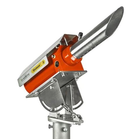
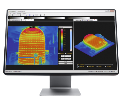
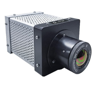
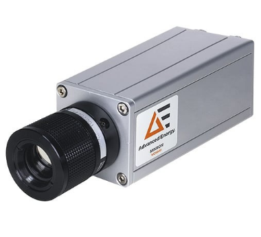
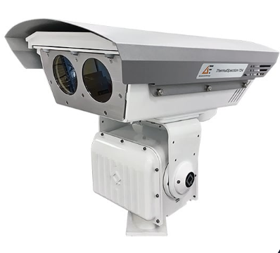
The ThermalSpection infrared thermal imaging system range combines radiometric cameras, industrial enclosures, control software and optional point sensors for continuous asset monitoring. ThermalSpection 724 is configured for electrical substations and industrial sites, using thermal and visual cameras on a remotely controlled pan-tilt unit. ThermalSpection CVM is intended for critical vessels such as gasifiers, reactors, storage tanks and process piping in chemical, refining and power applications.
Both configurations use 640 × 480 uncooled infrared detectors and provide automated alarm, archiving and trend functions. Available optics cover narrow and wide fields of view, allowing the monitored area to be matched to the target size and installation distance. Gigabit Ethernet, OPC, Modbus and configurable I/O support connection to DCS, SCADA and historian systems. Optional fixed imagers, pyrometers, local controllers and communication hubs allow each installation to be arranged around site access, blind spots and environmental conditions.
Range features
A high level overview of what this range offers
- Continuous automated thermal monitoring – Captures temperature changes and transient events without relying on inspection rounds.
- 640 × 480 uncooled infrared detector – Provides area-based radiometric measurement across equipment and vessel surfaces.
- Thermal and visual imaging on ThermalSpection 724 – Assists asset identification, camera positioning and interpretation of thermal events.
- Automatic hot-spot detection – Identifies the hottest location within configured regions as conditions change.
- Up to 32 regions of interest per camera – Allows separate limits and calculations to be applied to individual components or process areas.
- Continuous 360° pan and ±45° tilt on TS724DV-PT – Supports programmed inspection routes across multiple substation assets.
- Multiple optical configurations – Match the measurement field to different target dimensions and stand-off distances.
- Gigabit Ethernet, OPC and Modbus connectivity – Supports data exchange with DCS, SCADA and historian infrastructure.
- Alarm-triggered archiving with pre-buffer capability – Retains thermal information from immediately before and after an event.
- Multi-camera software packages – Support simultaneous connection of up to 24 cameras, depending on the selected package.
- Optional fixed imagers and pyrometers – Extend coverage to stationary targets and areas outside the main camera’s line of sight.
- Outdoor and hazardous-area enclosure options – Support installation in substations and classified process environments when correctly specified.
Downloads
for Thermalspection series
What’s in this range?
All the variants in the range and a comparison of what they offer
Specifications
| Specification | Value |
|---|---|
Product range | ThermalSpection 724 and ThermalSpection CVM |
Measurement principle | Non-contact infrared thermal imaging |
Detector | 640 × 480 uncooled microbolometer or focal plane array |
Range-level operating temperature | -40 to 60°C |
ThermalSpection 724 measurement range | -40 to 500°C |
ThermalSpection CVM measurement ranges | -40 to 120°C and 0 to 500°C; high-temperature option available |
Measurement accuracy | ±2°C or ±2% of reading; ThermalSpection 724 applies whichever is greater |
Wavelength range | 8000 to 14000 nm |
Filter or spectral band | 8 to 14 µm |
Measurement or image rate | 9 Hz or 50 Hz for CVM; variable by operating mode for 724 |
Field-of-view range | Approximately 8° to 77°, depending on model and lens |
Optical interface | 75 mm autofocus configuration; alternative manual or fixed-focus optics depending on model |
Range-level channel listing | 2 |
Emissivity correction | 0.1 to 1.0 |
Transmittance correction | 0.1 to 1.0 on CVM |
Regions of interest | Up to 32 per camera or tour stop |
Camera capacity | Up to 24 simultaneous cameras with the corresponding software package; a legacy 724 controller configuration lists up to 6 cameras per substation |
Communications | Gigabit Ethernet, OPC, Modbus serial, Modbus Ethernet, analogue outputs, digital I/O and relays |
Pan-tilt movement | Continuous 360° pan and ±45° tilt on TS724DV-PT; optional remote pan-tilt mechanism for CVM |
ThermalSpection 724 ambient range | -40 to 60°C with optional enclosure heater |
ThermalSpection 724 storage range | -40 to 75°C |
ThermalSpection CVM ambient range | 0 to 60°C; -40 to 60°C with optional heater |
ThermalSpection CVM storage range | -20 to 70°C |
Data and image functions | Live imaging, image and video capture, trend analysis, alarm archiving, historian connection and report export |
Variant comparison
| Specification | TS724DV-PT pan-tilt system | TS724 fixed imager | ThermalSpection CVM with MCL640 |
|---|---|---|---|
Primary application | Substation and industrial site monitoring | Fixed substation or industrial asset monitoring | Critical vessel and gasifier monitoring |
Thermal detector | 640 × 480 uncooled microbolometer | 640 × 480 uncooled microbolometer | 640 × 480 uncooled focal plane array |
Measurement range | -40 to 500°C | -40 to 500°C | -40 to 120°C and 0 to 500°C; high-temperature option available |
Accuracy | ±2°C or ±2%, whichever is greater | ±2°C or ±2%, whichever is greater | ±2°C or ±2% |
Field of view | 8.2° × 6.2° with 75 mm lens | 12°, 25°, 42° or 70° horizontal | 14° × 10°, 26° × 20°, 57° × 43° or 77° × 58° |
Focus | Autofocus | Fixed | Lens-dependent |
Image update rate | Variable by tour or alarm mode | Variable by operating mode | 9 Hz or 50 Hz |
Weight | 26 kg | Approximately 7 kg | Approximately 11 kg |
Communication | Gigabit Ethernet | Gigabit Ethernet | Gigabit Ethernet |
Power options | 220 VDC, 120 VAC or 230 VAC | 220 VDC, 120 VAC or 230 VAC | Universal AC input; DC optional |
Environmental provision | Substation-hardened enclosure and IP66 junction box | Weatherised enclosure with optional heater | Sealed, purged housing with cooling or optional heating |
Area classification | Not listed as a hazardous-area configuration | Not listed as a hazardous-area configuration | ATEX or Class I, Division 2 housing |
Visual camera | 768 × 576 progressive-scan CMOS camera | Not included | Not listed |
ThermalSpection 724 measurement field by lens and distance
| Object distance | TS724DV-PT 8° lens | TS724 12° lens | TS724 25° lens | TS724 42° lens | TS724 70° lens |
|---|---|---|---|---|---|
10 m | 1.4 × 1.1 m | 2.2 × 1.6 m | 4.3 × 3.3 m | 7.8 × 5.8 m | 14 × 10.5 m |
25 m | 3.6 × 2.7 m | 5.4 × 4.1 m | 10.9 × 8.2 m | 19.4 × 14.6 m | 35 × 26 m |
50 m | 7.2 × 5.4 m | 10.9 × 8.2 m | 21.7 × 16.3 m | 38.8 × 29.1 m | 70 × 52 m |
The measured object should cover at least 3 × 3 detector pixels for precise temperature determination.
FAQs
for Thermalspection series
Select ThermalSpection 724 for electrical substations and industrial sites where one camera position must inspect several distributed assets. Its TS724DV-PT assembly combines thermal and visual cameras with continuous 360° pan and ±45° tilt, while fixed TS724 imagers can cover permanently assigned targets. ThermalSpection CVM is configured for gasifiers and other high-temperature or high-pressure vessels requiring continuous surface-temperature mapping. Its purged hazardous-area housing and optional auxiliary pyrometers suit process installations with contamination, classified zones or obstructed views. The final choice should therefore follow the site classification, required viewing geometry, ambient conditions and control-system architecture.
Lens selection should begin with the physical size of the smallest component that must be measured, rather than the overall scene size alone. At a distance of 25 m, the TS724DV-PT 8° lens covers approximately 3.6 × 2.7 m, while the TS724 70° lens covers approximately 35 × 26 m. A narrower field of view places more detector pixels across a small target, whereas a wider lens covers more equipment but reduces spatial detail. The target should occupy at least 3 × 3 detector pixels to support precise temperature measurement. Engineers should check the measurement-field table against mounting distance, target movement, required thermal resolution and any future expansion of the monitored area.
ThermalSpection uses Gigabit Ethernet for camera and controller communication, with OPC, Modbus serial, Modbus Ethernet and physical I/O available through the software and interface modules. Calculated region temperatures, alarms and other processed values can therefore be transferred without sending the full thermal image into the control system. Analogue output modules, relays and digital I/O can support local alarms or process interlocks where required. Thermal images and temperature records can also be archived for trends, reports and event review, with optional connection to a PI database. Network segmentation, account permissions, historian tags and alarm priorities should be defined during the control-system design stage.
The TS724DV-PT uses a substation-hardened camera enclosure and an IP66 stainless-steel junction box, with an optional heater supporting ambient operation from -40 to 60°C. The fixed TS724 is supplied in a weatherised enclosure and uses the same stated ambient range when the optional heater is fitted. ThermalSpection CVM uses a sealed housing with an infrared-transparent window, internal cooling and positive-pressure purging to limit the entry of dirt or flammable gas. CVM field hardware is available in ATEX or Class I, Division 2 housings, with either a vortex air cooler or thermostat-controlled heater. Site engineers must still confirm the required area classification, purge utilities, cable entries and local installation rules before specification.
Accurate radiometric measurement depends on entering settings that reflect the target surface and the material between the target and camera. The thermal cameras provide emissivity correction from 0.1 to 1.0, while the CVM configuration also provides transmittance adjustment from 0.1 to 1.0 and ambient or background compensation. Low-emissivity bare metals can reflect surrounding heat and may not produce a representative surface-temperature reading without surface treatment or a validated correction method. Windows, steam, dust and process gases can also attenuate infrared energy and introduce additional uncertainty. Commissioning should therefore include comparison with a suitable reference, verification under normal process conditions and locked configuration control for critical measurement zones.
Current LumaSpec RT packages support simultaneous connection of up to 24 cameras, with the permitted number determined by the purchased software package. A legacy ThermalSpection 724 controller configuration lists up to six cameras at a substation, so the controller generation, licence and workstation specification should be confirmed when upgrading or extending an installation. Each camera supports up to 32 regions of interest, allowing separate minimum, maximum and average temperature calculations for different assets. The 724 auto-tour function supports up to 255 tour stops, with camera and region settings assigned to each stop. Network capacity, storage volume, tour cycle time and alarm response requirements should be calculated for the complete multi-camera system.
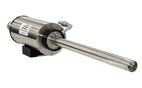
ThermalSpection 724 can be expanded with fixed TS724 imagers and IN 210 point pyrometers, while CVM supports auxiliary pyrometers for locations hidden from the main camera. The IN 210 measures from -32 to 900°C over an 8 to 14 µm spectral range and has an adjustable 120 ms response time. A standard 724 pyrometer kit contains five sensors, an IP66 stainless-steel junction box and five 30 m cables. Point sensors are useful for narrow gaps or obstructed components but do not provide the full temperature distribution available from a thermal image. Sensor placement should account for target size, emissivity, field of view, cable routing and maintenance access.
Calibration should be treated as part of the monitoring system’s maintenance plan rather than replaced by software correction alone. Available service levels include a standard two-point calibration and a certified calibration using five points or more with NIST certification. Between calibrations, maintenance should include inspection of infrared windows, enclosure seals, purge or cooling services, cables, junction boxes and camera alignment. Emissivity changes, dirty windows and altered transmission paths can resemble instrument drift, so a stable reference check is useful after cleaning or mechanical work. The calibration interval should be selected from process criticality, operating environment, drift history and the site’s quality procedures.