Mikron mcl640 series IR Camera
- Technology
- Thermal imagers
- Partner
- Advanced Energy
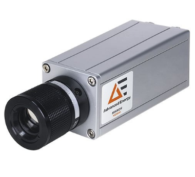
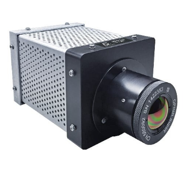
The Mikron MCL640 series is a long-wave infrared process camera for continuous temperature measurement and thermal-pattern monitoring. It comprises the MCL640L, with ranges of -40 to 120°C and 0 to 500°C, and the MCL640HT for measurements from 200 to 1600°C. A 640 × 480 detector provides 307,200 measurement pixels, supported by 16-bit A/D conversion and image update rates of 9 or 50 Hz. Five lens options cover nominal fields of view from 8° to 77° for narrow, long-distance views or wider process areas. Gigabit Ethernet connects the camera to LumaSpec RT software for image capture, analysis, alarm handling and plant-system integration.
Applications include electrical fault detection, refractory and ladle monitoring, furnaces, pipelines, gasifiers, casting processes, flare monitoring and PET preform inspection. The aluminium housing supports operation in any mounting position and uses a 12 VDC, 10 W supply. An optional cooled and purged enclosure supports installations exposed to weather, dust and ambient temperatures outside the camera housing’s standard 0 to 50°C operating range.
Range features
A high level overview of what this range offers
- 640 × 480 uncooled microbolometer array: Provides 307,200 pixels for area-based temperature monitoring.
- MCL640L and MCL640HT variants: Cover low-, medium- and high-temperature applications from -40 to 1600°C across the series.
- ±2°C or 2% measurement accuracy: Supports quantitative process monitoring when the application is configured correctly.
- 9 Hz or 50 Hz image update rate: Allows selection for steady processes or faster-moving targets.
- 16-bit A/D conversion: Provides detailed digital thermal data for analysis and recording.
- Five standard lens options: Cover nominal fields of view from 8° to 77°.
- Autofocus with the 75 mm lens: Supports remote focusing for narrow-field installations.
- Emissivity and transmittance correction from 0.1 to 1.0: Allows adjustment for target surfaces and optical paths.
- Gigabit Ethernet interface: Transfers thermal images and measurement data to the connected computer system.
- OPC, Modbus and optional physical I/O integration: Supports alarm and processed-data exchange with plant control systems.
- 12 VDC input with 10 W consumption: Supports integration into low-voltage industrial installations.
- Any-position operation: Provides flexibility when selecting the camera mounting orientation.
- CE and RoHS compliance: Helps equipment builders address applicable project and integration requirements.
- Optional cooled and purged enclosure: Extends installation possibilities into dusty, outdoor, hot or cold environments when correctly configured.
- LumaSpec RT Viewer software included: Provides an initial interface for camera viewing and operation.
Downloads
for Mikron mcl640 series IR Camera
What’s in this range?
All the variants in the range and a comparison of what they offer
Specifications
| Category | Specification | Value |
|---|---|---|
Measurement | Series temperature coverage | -40 to 1600°C across model variants |
Measurement | Measurement channels | 2 |
Measurement | Accuracy | ±2°C or 2% of reading |
Measurement | Image update rate | 9 Hz or 50 Hz |
Measurement | A/D resolution | 16 bit |
Measurement | Emissivity correction | 0.1 to 1.0 |
Measurement | Transmittance correction | 0.1 to 1.0 |
Detector | Detector type | Uncooled microbolometer array |
Detector | Detector resolution | 640 × 480 pixels |
Detector | Pixel pitch | 17 µm |
Spectral | Spectral range | 8 to 14 µm |
Optics | Lens options | 75, 50, 25, 11 and 8.2 mm |
Optics | Nominal field-of-view options | 8°, 14°, 26°, 57° and 77° |
Optics | Focus | 75 mm lens: autofocus; other lenses: manual |
Optics | Focus range | Lens-dependent |
Optics | Digital zoom | 1–8× through LumaSpec RT software |
Interface | Camera data interface | Gigabit Ethernet |
Interface | Connections | Four-pin power connection with pigtail; RJ45 Ethernet |
Integration | Supported system interfaces | OPC, Modbus serial, Modbus Ethernet, relays and analogue outputs through LumaSpec RT and applicable I/O hardware |
Environment | Camera operating temperature | 0 to 50°C at the housing |
Environment | Storage temperature | -20 to 70°C |
Environment | Relative humidity | Non-condensing |
Environment | Operating position | Any position |
Mechanical | Housing | 6063 T5 aluminium alloy with clear alodine finish to MIL-DTL-5541F |
Mechanical | Dimensions without lens | 127 × 101.6 × 101.6 mm |
Mechanical | Weight | 1 kg, excluding optional lens and protective enclosure |
Electrical | Power input | 12 VDC |
Electrical | Power consumption | 10 W |
Compliance | Compliance | CE and RoHS |
Delivery | Included items | Power connector with 30 mm pigtail, electronic manual, carrying case and LumaSpec RT Viewer software |
Options | Installation accessories | Industrial power supply, tabletop power supply and vortex air-cooled enclosure |
Variant comparison
| Specification | MCL640L | MCL640HT |
|---|---|---|
Spectral filter | 8 to 14 µm | 8 to 14 µm |
Temperature range 1 | -40 to 120°C | 200 to 1600°C |
Temperature range 2 | 0 to 500°C | — |
Fahrenheit range 1 | -40 to 248°F | 392 to 2912°F |
Fahrenheit range 2 | 32 to 932°F | — |
Metric measurement field values are shown as width × height.
Lens field of view by distance
| Object distance | 8° lens, 75 mm | 14° lens, 50 mm | 26° lens, 25 mm | 57° lens, 11 mm | 77° lens, 8.2 mm |
|---|---|---|---|---|---|
10 m | 1.4 × 1.1 m | 2.2 × 1.6 m | 4.3 × 3.3 m | 9.8 × 7.4 m | 13.6 × 10.2 m |
25 m | 3.6 × 2.7 m | 5.4 × 4.1 m | 10.9 × 8.2 m | 24.7 × 18.5 m | 34 × 25.5 m |
50 m | 7.2 × 5.4 m | 10.9 × 8.2 m | 21.7 × 16.3 m | 49.5 × 37.1 m | 68 × 51 m |
FAQs
for Mikron mcl640 series IR Camera
The choice is primarily determined by the expected minimum and maximum process temperatures. The MCL640L is specified with ranges of -40 to 120°C and 0 to 500°C, making it suitable for lower-temperature equipment, electrical monitoring and many general industrial processes. The MCL640HT covers 200 to 1600°C for hotter targets such as refractory surfaces and high-temperature process equipment. Both variants operate in the 8 to 14 µm long-wave infrared band and use the same 640 × 480 detector format. Selection should include sufficient margin around normal and abnormal process conditions rather than relying on operation at the exact limit of a range.
Lens selection depends on the target size, working distance and required spatial detail. At 10 m, the 75 mm lens covers approximately 1.4 × 1.1 m, while the 8.2 mm lens covers approximately 13.6 × 10.2 m. At 50 m, those fields increase to 7.2 × 5.4 m and 68 × 51 m respectively, so a wide lens observes more of the process but allocates fewer pixels to a small target. The 75 mm lens provides autofocus, whereas the other standard lenses are manually focused. If the optional VC enclosure is required, its compatibility list covers the 14°, 26°, 57° and 77° MCL640 lenses, so the 8° option requires separate installation confirmation.
The 50 Hz option is appropriate where the thermal scene changes quickly or products move rapidly through the field of view. PET preform monitoring is one example, as the camera can acquire temperature data at 50 frames per second while parts pass through the production process. A 9 Hz version can be sufficient for slower processes such as fixed-equipment monitoring, gradual refractory heating or general condition surveillance. Frame rate should be considered alongside network traffic, computer performance, archive requirements and the number of connected cameras. It should not be treated as a substitute for confirming the complete system response time required by the control application.
The measurement accuracy is specified as ±2°C or 2% of the reading. At 500°C, a 2% term corresponds to 10°C, while at 1600°C it corresponds to 32°C; the governing convention should therefore be confirmed when establishing contractual acceptance limits. Application uncertainty can also be affected by emissivity, reflected background energy, atmospheric transmission, viewing windows, focus and the number of pixels filled by the target. The available emissivity and transmittance adjustments help compensate for known conditions but do not remove the need for a controlled measurement setup. Where process tolerances are tight, the complete uncertainty budget should be assessed at the actual target temperature and installation geometry.
The camera transfers thermal images and measurement data through a Gigabit Ethernet connection using an RJ45 interface. LumaSpec RT can process the data and pass alarms or calculated values to plant systems through OPC, serial or Ethernet Modbus, relays and analogue outputs, depending on the selected software and I/O configuration. This architecture allows the thermal camera to act as an area sensor while the software converts regions of interest into control-system values. Multi-camera software packages support up to 24 simultaneous cameras, subject to the selected package and computer capacity. Engineers should define network segmentation, data rates, alarm logic, fail-safe behaviour and time synchronisation before commissioning the control link.
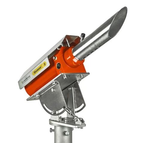
The camera housing itself is specified for operation from 0 to 50°C under non-condensing conditions, so additional protection is required when the ambient environment exceeds those limits. The optional VC enclosure is rated IP66 and NEMA 4X, uses integrated air cooling and includes a window-purge connection to limit contamination. Its operating range is 0 to 65°C, extending to -40 to 65°C when the heater arrangement is fitted. Cooling requires approximately 15 cfm of air at 90 to 100 psi, and the enclosure weighs about 11 kg before mounting hardware is considered. Optional Type X and Type Z purge arrangements are available for hazardous-area projects, but the complete installation and certification basis must be checked for the specific site.
The camera measures infrared radiation rather than surface temperature directly, so the configured emissivity must represent how efficiently the target emits energy in the 8 to 14 µm band. Both emissivity and transmittance can be adjusted from 0.1 to 1.0, allowing compensation for target characteristics and losses through an optical path or window. Incorrect settings can create systematic errors even when the camera operates within its stated range and accuracy. Reflective metals, changing surface finishes and contaminated viewing windows require particular attention because their apparent radiation can vary during production. Practical commissioning should therefore include representative target conditions, stable viewing geometry and comparison against an accepted temperature reference where possible.
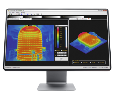
LumaSpec RT provides live image viewing, image and video capture, temperature profiles, histograms, isotherms, hot- and cold-spot detection, trend displays and region-of-interest analysis. Depending on the software package, a region can report minimum, maximum, average and standard-deviation temperatures and can be linked to alarms or plant-system outputs. The software also supports up to 8× digital zoom, data export and the review of recorded images and sequences. LumaSpec RT Viewer is included with the camera, while additional analysis, control and multi-camera functions depend on the selected software edition. The required edition should be chosen according to the intended number of cameras, alarm logic, archiving needs and PLC or DCS integration requirements.