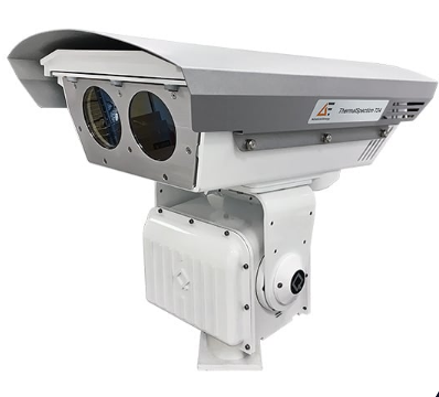
Flarespection IR camera system
- Technology
- Flare monitoring cameras
- Partner
- Advanced Energy
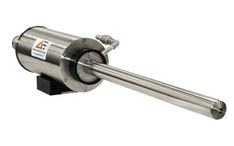
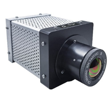
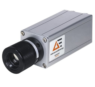
The FlareSpection infrared camera system is a fixed thermal imaging solution for continuous remote monitoring of pilot flames and flare stack combustion. It is designed for oil, gas, petrochemical, chemical and other process sites where operators must distinguish multiple heat signatures and confirm pilot status remotely. A 640 × 480 uncooled microbolometer, 200 mm telephoto lens and 3° × 2.3° field of view provide detailed thermal images at distances up to 300 m.
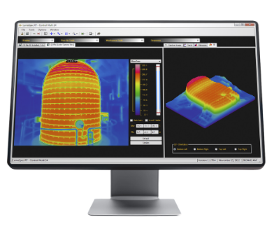
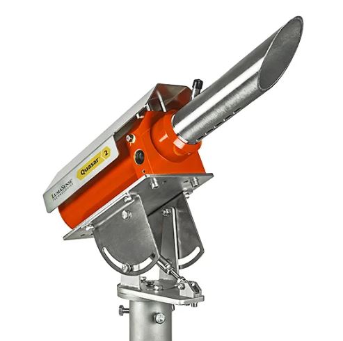
The system can monitor an individual pilot while the main flare is present and detect a range of flame types, including hydrogen flames. Its 316L stainless-steel housing carries hazardous-area classifications for ATEX, IECEx, the United States and Canada. Monitoring software provides automated analysis, alarms, scene registration, video recording, event archiving and plant-network viewing for systems with up to 24 cameras. OPC, Modbus serial, Modbus Ethernet, analogue contact outputs and relays enable integration with DCS, PLC and pilot ignition arrangements.
Range features
A high level overview of what this range offers
- 640 × 480 uncooled microbolometer: Provides detailed thermal images for separating pilot and flare heat signatures.
- 200 mm telephoto lens: Supports remote flare monitoring at distances up to 300 m.
- 3° × 2.3° field of view: Concentrates the image on defined flare and pilot regions.
- 1 to 8× digital zoom: Assists with software-based inspection of selected image areas.
- 9 Hz image update rate: Provides continuous image refresh for automated monitoring.
- Individual pilot monitoring: Identifies pilot status while the main flare is present.
- Hydrogen flame detection: Supports applications involving a wider range of flare gases.
- 316L stainless-steel enclosure and sight tube: Resists corrosion and limits contamination of the viewing window.
- ATEX, IECEx, US and Canadian hazardous-area classifications: Supports installation in appropriately matched classified areas.
- NEMA 4X and IP66 protection: Protects the camera assembly against outdoor environmental exposure.
- Automated alarms and scene registration: Maintains defined monitoring areas as a flare stack moves or sways.
- OPC, Modbus and physical outputs: Supports integration with plant DCS, PLC and pilot ignition systems.
- Video, event and alarm archiving: Provides historical records for investigation and operational review.
- Support for up to 24 cameras: Enables centralized monitoring of larger or multi-flare installations.
Downloads
for Flarespection IR camera system
What’s in this range?
All the variants in the range and a comparison of what they offer
| Specification | Value |
|---|---|
Image update rate | 9 Hz |
Pixel pitch | 17 µm |
Detector | 640 × 480 uncooled microbolometer |
Monitoring capability | Continuous flare and pilot flame monitoring |
Flame types | Wide range, including hydrogen flames |
Recommended maximum monitoring distance | Up to 300 m |
Lens focal length | 200 mm |
Field of view | 3° horizontal × 2.3° vertical |
Digital zoom | 1 to 8× through LumaSpec RT software |
Communication and outputs | OPC, Modbus serial, Modbus Ethernet, analogue contact outputs and relays |
Power input | 24 VDC |
ATEX classification | II 2 G Ex db IIB T4 |
IECEx classification | Ex db IIB T4 |
US and Canadian classification | Class 1, Division 1, Groups C and D, T4; Class 1, Division 2, Groups A, B, C and D, T4 |
Environmental protection | NEMA 4X; IP66 |
Operating temperature | -30 to 50°C (-22 to 122°F) |
Storage temperature | -20 to 70°C (-4 to 158°F) |
Weight | Approximately 38 kg (84 lb) |
Housing | 316L stainless steel, certified for hazardous areas and suitable for marine applications |
Multi-camera capacity | Up to 24 cameras |
Software functions | Automated image analysis, alarms, scene registration, video retrieval, file or database archiving and network viewing |
Standard scope of supply | Camera with 200 mm lens; enclosure with sunshield and sight tube; flare and pilot monitoring software; adjustable stainless-steel pan-and-tilt mount |
Optional accessories | Stainless-steel base, junction box, DCS and pilot-ignition I/O module, computer server and SQL-based data historian |
FAQs
for Flarespection IR camera system
Yes, provided each flame occupies a resolvable area within the camera view. The 640 × 480 uncooled microbolometer, 17 µm pixel pitch and 200 mm telephoto lens provide a 3° × 2.3° field of view, allowing the software to separate heat signatures within the scene. Individual pilots can be monitored while the main flame is present, and the system is intended for multiple-pilot or closely spaced flare arrangements. Scene-registration tools can maintain analysis alignment when the stack moves or sways. Camera quantity and viewpoints should still be determined from stack geometry, pilot orientation, wind movement and possible line-of-sight obstructions.
The camera can monitor from distances up to 300 m, but its final position should be established through a site survey. The 200 mm lens and 3° × 2.3° field of view create a narrow viewing area, so the selected location must provide clear coverage of every required pilot and flare region. The survey should record the stack height, flare-tip orientation, number of pilots, proposed camera distance, prevailing wind direction, hazardous-area classification and ambient temperature. A rigid mounting foundation is important because small angular changes become more significant over long distances. Complex stacks may require several viewpoints rather than one camera.
Yes, when the installation classification matches the stated approvals and environmental limits. The system carries ATEX II 2 G Ex db IIB T4 and IECEx Ex db IIB T4 classifications, together with US and Canadian Class 1 Division 1 and Division 2 ratings for the listed gas groups. Its 316L stainless-steel housing is rated NEMA 4X and IP66, with a specified operating range of -30 to 50°C. The project engineer must still verify the applicable gas group, temperature class, division or zone, cable entries, power arrangements and local installation rules. The enclosure rating should not be treated as automatic approval for every classified location.
The system supports OPC, Modbus serial, Modbus Ethernet, analogue contact outputs and relays. These interfaces allow pilot status, flare condition, alarms and processed image results to be passed to a plant DCS, PLC or pilot ignition arrangement. The camera system requires a 24 VDC power input, while an optional I/O module can provide connections for hard-wired control and alarm functions. Files and processed data can also be transferred to a data historian when the appropriate server and database architecture are installed. The selected interface should match the required response, redundancy, cybersecurity and plant-standard communication practices.
It can be engineered as an independent, non-contact monitoring method or as a backup to conventional thermocouples. Because it observes heat signatures remotely, it can continue reporting pilot and flare status when a thermocouple at the flare tip fails. It also avoids placing the primary sensing device directly within the flare-stack environment and can monitor several pilots from one or more ground-mounted locations. However, replacing an existing protection or control instrument requires a site-specific functional safety and regulatory assessment. Alarm logic, voting arrangements, proof testing and failure responses should be defined before the thermal imaging signal is assigned a safety-related role.
A Windows-based host is required for live image acquisition, automated analysis, alarm handling and archiving. The software can support up to 24 cameras, allowing several flare views to be displayed and managed from a central workstation or plant network. Recorded images, video, events and alarm data may be archived to files or a database, while an optional server and SQL-based historian can support longer-term storage. Scene registration helps maintain image-analysis alignment when the stack moves, and plant interfaces can deliver processed results to the DCS or PLC. Storage capacity, network bandwidth, user access and software licence level should be defined during system design.
The standard scope includes the FlareSpection camera with a 200 mm lens, a stainless-steel enclosure with sunshield and sight tube, flare and pilot monitoring software, and an adjustable stainless-steel pan-and-tilt mount. Optional equipment includes a stainless-steel base, field junction box, I/O module, automation server and SQL-based data historian. These options affect the mechanical installation, cable marshalling, control-system interface and data-retention architecture. Projects involving several cameras may also require network switches, additional server resources and suitable operator displays. The final bill of materials should therefore be based on the number of viewpoints, required outputs and plant-network arrangement.
Remote mounting and the integrated sight tube reduce routine access requirements, but they do not remove the need for inspection. Maintenance planning should cover window cleanliness, sight-tube condition, mounting security, alignment, enclosure seals, cable entries, network health and alarm operation. The adjustable stainless-steel mount and scene-registration function help preserve the monitoring view, while the NEMA 4X, IP66 and 316L construction protect the installed hardware. Any work within a hazardous area must follow the site’s permit, isolation and inspection procedures. Inspection and functional-test intervals should be selected according to environmental exposure, process criticality and the role assigned to each alarm.