Mikron mcs640 series IR camera
- Technology
- Thermal imagers
- Partner
- Advanced Energy
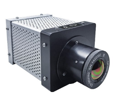
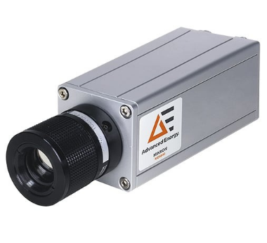
The Mikron MCS640 Series IR camera measures and visualises temperature distributions in high-temperature manufacturing processes without contacting the target. It is designed for melting, rolling, forging, hardening, annealing, induction heating, welding and continuous casting applications. Short-wavelength detection helps limit the influence of reflected thermal radiation when working with hot metal, graphite and ceramic surfaces. Interchangeable manual-focus optics provide fields of view for wide-area observation, small targets and microscopic measurement tasks.
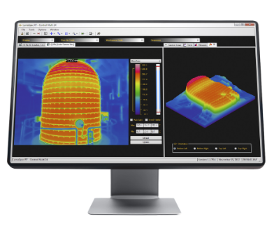
The standard MCS640 has an IP65 and NEMA 4 aluminium enclosure, weighs 0.7 kg and operates at ambient temperatures from 0 to 50°C. The MCS640-HD weighs approximately 3.0 kg, depending on its lens configuration, and can be combined with a water-cooled enclosure where additional thermal protection is required. LumaSpec RT software provides image recording, regions of interest, alarms, temperature trends, data export and industrial communication functions.
Range features
A high level overview of what this range offers
- Short-wavelength infrared sensing – Reduces interference from reflected thermal radiation when measuring hot metals, graphite and ceramics.
- 600 to 1600°C and 800 to 3000°C bands – Supports a broad range of high-temperature thermal processes.
- 640 × 480 silicon detector – Captures area temperature distributions and supports measurement of small targets.
- 60 Hz image acquisition – Records changing thermal patterns at intervals of approximately 16.7 ms.
- Adjustable emissivity from 10.0 to 100.0% – Allows the measurement configuration to be matched to the target surface.
- Adjustable transmittance from 10 to 100% – Supports software compensation for viewing windows and transmission losses.
- Gigabit Ethernet interface – Enables real-time network transmission and remote camera operation.
- Manual-focus lens options from approximately 3.5° to 41° – Adapt the field of view to the target size and installation distance.
- IP65 and NEMA 4 camera housing – Protects the standard camera in fixed industrial installations.
- LumaSpec RT compatibility – Adds regions of interest, alarm processing, sequence capture, analysis and control-system integration.
- MCS640-HD and compatible protective enclosures – Provide installation options for elevated ambient temperatures and contaminated environments.
What’s in this range?
All the variants in the range and a comparison of what they offer
Specifications
| Category | Specification | Value |
|---|---|---|
Measurement | Technology | Short-wavelength infrared thermal imaging with internal digital signal processing |
Measurement | Standard temperature range, MB16 | 600 to 1600°C |
Measurement | Standard temperature range, MB30 | 800 to 3000°C in up to four subranges |
Measurement | MB16 subranges | 600 to 850°C; 700 to 1000°C; 850 to 1250°C; 1100 to 1600°C |
Measurement | MB30 subranges | 800 to 1150°C; 1000 to 1500°C; 1350 to 2050°C; 1900 to 3000°C |
Measurement | Spectral configurations | I5: 780 to 1080 nm; I1: 850 nm; V: 650 nm; I4: 750 nm; I8: 1080 nm |
Measurement | Number of channels | 1 |
Measurement | Detector | 640 × 480 pixels, silicon |
Measurement | Sensitivity / NETD | 1°C at 600°C |
Measurement | Image update rate | 60 Hz |
Measurement | Emissivity adjustment | 10.0 to 100.0% in 0.1% steps for the full-frame image |
Measurement | Transmittance adjustment | 10 to 100% through the application software |
Measurement | Measurement uncertainty | ±0.5% of reading in kelvin; an alternate series specification states ±2°C or 2% of reading, so confirm the applicable value for the ordered configuration |
Measurement | Repeatability | 0.1% of the measured value in kelvin plus 1 K |
Optics | Focus | Manual |
Optics | Field-of-view range | Approximately 3.5° to 41°, depending on the selected lens |
Optics | Minimum target coverage | At least 3 × 3 detector pixels for temperature determination |
Interface | Digital interface | Gigabit Ethernet, 1000 Mbit/s |
Interface | Connections | 12-pin power connector and RJ45 Ethernet connector |
Interface | Software and control integration | OPC DA 2.0, Modbus TCP/IP, Modbus serial, Modbus Ethernet and optional analogue or digital I/O functions through the software and external I/O architecture |
Electrical | Supply | 24 VDC, 1 A |
Electrical | Power consumption | 10 W typical, 13 W maximum |
Electrical | Direct analogue output | None |
Environmental | Operating ambient temperature | 0 to 50°C |
Environmental | Storage temperature | -40 to 70°C |
Environmental | Relative humidity | Non-condensing conditions |
Mechanical | MCS640 weight | 0.7 kg |
Mechanical | MCS640-HD weight | Approximately 3.0 kg, dependent on the final lens configuration |
Mechanical | Housing | Aluminium extrusion |
Protection | Protection class | IP65 in accordance with IEC 60529; NEMA 4 |
Protection | Shock resistance | 30 G in accordance with IEC 60068-2-29 and JIS C 0042 |
Protection | Vibration resistance | 3 G in accordance with IEC 60068-2-6 and JIS C 0040 |
Compliance | CE marking | In accordance with applicable EU directives concerning electromagnetic immunity |
Optical Measurement Field
| Object distance | 3.5° × 2.6° | 5.4° × 4.0° | 10.8° × 8.1° | 22.5° × 17.0° | 33.3° × 25.3° | 40.4° × 30.9° |
|---|---|---|---|---|---|---|
1.00 m | 0.06 × 0.05 m | 0.09 × 0.07 m | 0.19 × 0.14 m | 0.40 × 0.30 m | 0.60 × 0.45 m | 0.74 × 0.55 m |
1.50 m | 0.09 × 0.07 m | 0.14 × 0.10 m | 0.28 × 0.21 m | 0.60 × 0.45 m | 0.90 × 0.67 m | 1.10 × 0.83 m |
2.50 m | 0.15 × 0.11 m | 0.24 × 0.17 m | 0.47 × 0.35 m | 0.99 × 0.75 m | 1.50 × 1.12 m | 1.84 × 1.38 m |
10.00 m | 0.61 × 0.45 m | 0.94 × 0.70 m | 1.91 × 1.43 m | 3.98 × 2.99 m | 5.98 × 4.49 m | 7.36 × 5.53 m |
Measurement fields are stated as width × height. The target should cover at least 3 × 3 pixels, with additional coverage allowed for movement, vibration and alignment tolerances. Measurement distances may require further review in installations with particularly high radiant heat.
Variant and Reference Number Table
| Lens, image rate and temperature range | MCS640/I5, 780 to 1080 nm | MCS640/I1, 850 nm | MCS640-HD/I5, 780 to 1080 nm | MCS640HD/I1, 850 nm |
|---|---|---|---|---|
Standard lens, 10.8° × 8.1°, 60 Hz, 600 to 1600°C | 461H1625 | 461J1625 | 461H1625-HD | 461J1625-HD |
Wide-angle lens, 33.3° × 25.3°, 60 Hz, 600 to 1600°C | 461H1608 | 461J1608 | 461H1608-HD | 461J1608-HD |
Wide-angle lens, 22.5° × 17.0°, 60 Hz, 600 to 1600°C | 461H1612 | 461J1612 | 461H1612-HD | 461J1612-HD |
Telephoto lens, 5.4° × 4.0°, 60 Hz, 600 to 1600°C | 461H1650 | 461J1650 | 461H1650-HD | 461J1650-HD |
Telephoto lens, 3.5° × 2.6°, 60 Hz, 600 to 1600°C | 461H1675 | 461J1675 | 461H1675-HD | 461J1675-HD |
Standard lens, 10.8° × 8.1°, 60 Hz, 800 to 3000°C | 461H3025 | 461J3025 | 461H3025-HD | 461J3025-HD |
Wide-angle lens, 33.3° × 25.3°, 60 Hz, 800 to 3000°C | 461H3008 | 461J3008 | 461H3008-HD | 461J3008-HD |
Wide-angle lens, 22.5° × 17.0°, 60 Hz, 800 to 3000°C | 461H3012 | 461J3012 | 461H3012-HD | 461J3012-HD |
Telephoto lens, 5.4° × 4.0°, 60 Hz, 800 to 3000°C | 461H3050 | 461J3050 | 461H3050-HD | 461J3050-HD |
Telephoto lens, 3.5° × 2.6°, 60 Hz, 800 to 3000°C | 461H3075 | 461J3075 | 461H3075-HD | 461J3075-HD |
FAQs
for Mikron mcs640 series IR camera
Choose MB16 when the complete process falls between 600 and 1600°C, and choose MB30 when measurement must extend from 800 to 3000°C. Each band is divided into four overlapping subranges, allowing the camera to be configured around the expected operating window rather than the entire span. Filter selection is separate from temperature-range selection: I5 covers 780 to 1080 nm, while I1 operates at 850 nm and is identified for clean-gas flame furnaces. The V, I4 and I8 versions provide 650, 750 and 1080 nm configurations for applications with different spectral requirements. The ordered range and filter should therefore be checked against the target temperature, atmosphere, viewing window and line of sight.
Shorter operating wavelengths can reduce measurement errors associated with reflected radiation and an incorrect emissivity setting on hot metallic surfaces. This is relevant to steel, graphite and ceramic processes, where the target may be reflective and surrounding equipment can also be at a high temperature. The MCS640 is a single-channel instrument, so emissivity must still be configured correctly between 10.0 and 100.0%, while software transmittance can be adjusted between 10 and 100%. Stable surface condition, a clean optical path and a representative emissivity value remain important. If emissivity changes substantially during the process, the installation should be validated against a reference measurement or supplemented by ratio pyrometry where appropriate.
Lens selection should begin with the target dimensions, camera distance and the amount of surrounding process area that must remain visible. Available fields of view range from approximately 3.5° × 2.6° to 40.4° × 30.9°, with manual focus and additional microscopic options for particularly small objects. At a distance of 1 m, the 22.5° × 17.0° lens covers an area of 0.40 × 0.30 m, corresponding to approximately 0.625 mm per pixel in each direction. The target must cover at least 3 × 3 pixels, which represents roughly 1.9 × 1.9 mm in that example. A larger pixel margin should be used where the target moves, vibrates or cannot be aligned consistently.
A 60 Hz image rate produces a new thermal frame approximately every 16.7 ms, making the camera applicable to many rolling, induction-heating, welding and forming operations. LumaSpec RT can display the thermal stream in real time, record individual frames or sequences and evaluate point, line and area regions of interest. Alarm conditions can be based on minimum, maximum or average temperatures, and they can initiate capture or external actions through the available I/O architecture. The 60 Hz frame rate should not be treated as the complete control-loop response time because software processing, networking and the plant controller introduce additional latency. End-to-end response should be tested under actual network load when the measurement is part of a fast closed-loop control system.
The camera uses a 1000 Mbit/s Gigabit Ethernet connection through an RJ45 port, with power supplied separately through a 12-pin connector at 24 VDC and 1 A. Typical power consumption is 10 W, rising to a stated maximum of 13 W. There is no direct analogue output on the camera, so analogue signals, relays and triggering require compatible external I/O modules and the LumaSpec RT software architecture. OPC DA 2.0 and Modbus functions are available for exchanging temperature and alarm information with supervisory or control systems. For multi-camera installations, the network design should account for continuous image traffic, jumbo-frame support and the required separation from other plant data.
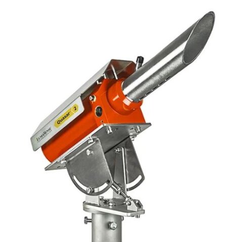
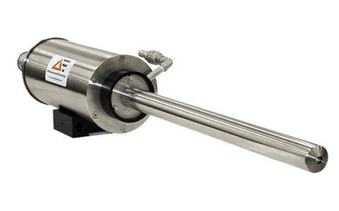
The standard MCS640 operates from 0 to 50°C and uses an aluminium IP65 and NEMA 4 housing rated for 30 G shock and 3 G vibration. The MCS640-HD adds a heavier enclosure arrangement and can be paired with water cooling when ambient temperatures exceed the standard camera limit. A compatible VC vortex-cooled enclosure is rated from 0 to 65°C, or down to -40°C when its optional heater is used, and provides IP66 and NEMA 4X protection. Vortex cooling requires approximately 15 cfm of compressed air at 90 to 100 psi, so air quality, pressure stability and operating cost should be assessed during installation planning. Hazardous-area purge options are available, but their approvals apply to the enclosure and purge arrangement rather than automatically certifying the complete camera installation.
The detailed technical specification gives a measurement uncertainty of ±0.5% of the reading in kelvin and repeatability of 0.1% of the measured value in kelvin plus 1 K. A separate series-level specification states ±2°C or 2% of reading, creating a difference that should be resolved for the exact part number before an acceptance criterion is written. Emissivity, transmittance, reflected temperature, optical cleanliness and target coverage can introduce additional application errors beyond the camera rating. Standard two-point calibration and certified calibration at five or more points with NIST certification are available as service options. For a traceable installation, calibration points should bracket the normal process range and the ordered configuration should be recorded in the measurement plan.
LumaSpec RT supports live image display, frame capture, sequence recording and temperature analysis within point, line and area regions of interest. Available tools include histograms, three-dimensional profiles, line profiles, temperature trends, image subtraction, auto-gain and up to 8× digital zoom. The software can generate alarms from minimum, maximum or average ROI temperatures and export data to text or spreadsheet-compatible formats. Multi-camera operation, OPC, Modbus TCP/IP, web-server functions and optional software development tools are also supported. Recorded images can be transferred to LumaSpec Offline Analyzer for further filtering, isotherm analysis, image processing and report preparation without occupying the live monitoring system.