ProScan III microscope controllers & joysticks
- Technology
- Photonics accessories
- Partner
- Prior Scientific
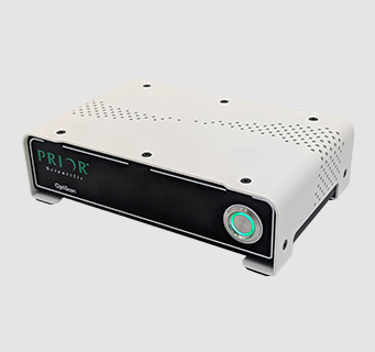
ProScan III is a configurable microscope automation controller range for coordinating motorised positioning and optical peripherals. It is intended for automated upright and inverted microscope systems, imaging workstations and OEM instruments. Depending on the selected configuration, the controller can operate an XY stage, focus axis, filter wheels, shutters, illumination devices and selected custom stepper-motor axes. A base cube supports a typical three-axis stage-and-focus arrangement, while ancillary modules extend the available functions.
Host control is available through USB and RS232C, with SDK support for integration into imaging or instrument software. CS200XY and CS200Z controls provide separate manual operation of the stage and focus, allowing both to be adjusted from independent desk-mounted units. This is a configurable range rather than a single fixed product, so the controller code should be matched to the required motors, encoders, triggers and peripherals before ordering.
Range features
A high level overview of what this range offers
- Up to nine controlled axes – Brings multiple microscope motion and optical functions into one control system.
- Three-axis base unit – Covers a typical motorised XY stage and Z-focus arrangement.
- Ancillary expansion modules – Add filter-wheel, shutter, trigger or OEM-axis capacity as the system develops.
- USB and RS232C host control – Supports PC integration and command-based automation.
- Programmable TTL I/O on suitable configurations – Enables synchronisation with cameras and external equipment.
- Adjustable speed, acceleration and drive current – Allows motion characteristics to be matched to the connected mechanism.
- Optional encoder inputs – Support closed-loop positioning with compatible stages and focus systems.
- Stage-stored configuration data and IST – Applies stage-specific movement compensation automatically.
- Automatic accessory detection – Reduces manual configuration for supported stages and joystick controls.
- Separate CS200XY and CS200Z controls – Allows two-handed operation of stage position and focus.
- 90 × 90 mm joystick footprint with daisy-chain connection – Supports flexible left- or right-hand placement.
- Local speed adjustment and programmable buttons – Places routine operator controls close to the microscope.
What’s in this range?
All the variants in the range and a comparison of what they offer
General controller and joystick specifications
| Specification | Details |
|---|---|
Maximum controlled axes | Up to 9 |
Custom OEM axes | Up to 6 configurable OEM axes |
Base controller capacity | Three-axis system, typically motorised XY stage and Z focus |
Typical controlled equipment | Motorised stages, focus devices, filter wheels, shutters, illumination equipment and selected OEM stepper axes |
Expansion | One or more ancillary modules in a horizontal or vertical arrangement |
Motor configuration | Individual speed, acceleration and drive-current settings |
Encoder support | Optional encoder feedback for compatible stage and focus axes |
Computer interfaces | USB virtual COM and RS232C |
RS232 ports | 2 |
Serial format | 8 data bits, 1 stop bit, no parity and no handshake |
Baud-rate options | 9,600, 19,200, 38,400 and 115,200 baud |
Additional control connections | CS200 joystick, CAN bus and TTL, depending on controller configuration |
Programmable TTL I/O | 4 programmable TTL inputs and 4 programmable TTL outputs on compatible configurations |
Software integration | SDK for third-party software integration |
Mains input | 110/240 VAC, 50–60 Hz |
Controller dimensions | 177 × 177 × 177 mm |
Ancillary module size | Adds 59 mm to the assembled controller configuration |
Controller weight | 3 kg |
Ancillary module weight | 1 kg |
Supported stage speed | Up to 300 mm/s, depending on the connected stage |
Commanded step size | From 0.01 µm for XY and 0.002 µm for Z |
Stage/focus repeatability | Typically less than 1 µm, depending on the connected mechanics |
Linear scale options | 0.1 µm or 0.05 µm |
Compatible ball-screw options | Ground recirculating ball screws with 1, 2, 4 or 5 mm pitch |
Limit-switch options | Adjustable in X and Y; optical or mechanical options in Z |
CS200XY function | Manual XY control for compatible motorised stages |
CS200Z function | Manual Z-axis control for compatible focus devices |
CS200 control footprint | 90 × 90 mm |
CS200 speed control | Side-mounted speed adjustment on CS200XY and CS200Z |
CS200 connection | Daisy-chain connection with automatic detection at power-up |
Optional touchscreen control | TS200 touchscreen interface for system control and parameter configuration |
Stepper-stage and peripheral controller variants
| Specification | H31ZFE / V31F | H31XYZE / V31XYZE | V31XYZET | H31XYZEF / V31XYZEF | V31XYZEFT | V31XYZEF2 |
|---|---|---|---|---|---|---|
Primary use | Focus and optical peripherals, or optical peripherals only | Stage and focus | Stage, focus and triggering | Stage, focus and optical peripherals | Stage, focus, optical peripherals and triggering | Stage, focus and expanded optical peripherals |
XY stepper stage | No | Yes | Yes | Yes | Yes | Yes |
Z focus, excluding piezo | H31ZFE: yes; V31F: no | Yes | Yes | Yes | Yes | Yes |
Encoder support | H31ZFE focus input; not applicable to V31F | Yes | Yes | Yes | Yes | Yes |
Filter-wheel drives | H31ZFE: 2 with focus or 3 without; V31F: 3 | None | None | 3 | 3 | 6 |
Shutter drives | 3 | None | None | 3 | 3 | 6 |
Trigger board | No | No | Yes | No | Yes | No |
Linear-stage controller variants
| Specification | HLD31XYZG / VLD31XYZG | VLD31XYZFG | VLD31XYZTG | VLD31XYZFTG |
|---|---|---|---|---|
Primary use | Linear XY stage and focus | Linear stage, focus and optical peripherals | Linear stage, focus and triggering | Linear stage, focus, optical peripherals and triggering |
XY linear stage | Yes | Yes | Yes | Yes |
Z focus, excluding piezo | Yes | Yes | Yes | Yes |
Encoder support | Yes | Yes | Yes | Yes |
Filter-wheel drives | None | 3 | None | 3 |
Shutter drives | None | 3 | None | 3 |
Trigger board | No | No | Yes | Yes |
FAQs
for ProScan III microscope controllers & joysticks
Select the controller by listing every motorised axis and peripheral that must be operated. H31XYZE or V31XYZE suits a stepper-driven XY stage plus non-piezo Z focus with encoder support, while H31ZFE provides focus and optical-peripheral control and V31F is intended for filter and shutter functions without an XY stage. H31XYZEF or V31XYZEF combines stage, focus, encoders, three filter wheels and three shutters. V31XYZEFT adds a trigger board, whereas V31XYZEF2 extends capacity to six filter wheels and six shutters. This selection process helps prevent missing control channels or ordering functions that the instrument will not use.
The range can coordinate up to nine controlled axes, depending on the selected modules and connected equipment. The base unit is intended for three axes, normally an XY stage and Z-focus mechanism. Ancillary modules add filter-wheel or OEM motor channels, and more than one module can be installed where additional capacity is required. Up to six axes can be configured for OEM applications, with speed, acceleration and drive current set individually. Engineers should prepare an axis schedule that separates stepper motors, encoder feedback, shutters, trigger I/O and illumination control because these functions require different connections and do not all consume the same type of channel.
Host control is available over USB virtual COM and RS232C. Serial operation uses eight data bits, one stop bit, no parity and no handshake, with 9,600, 19,200, 38,400 and 115,200 baud options. Full configurations provide two RS232 ports and include USB, CAN bus, joystick and TTL connections, although the fitted connectors depend on the ordered version. Trigger-equipped models provide programmable TTL inputs and outputs for coordinating motion or optical devices with external equipment. For software integration, use the supplied SDK and confirm that the selected imaging package supports every required accessory rather than stage movement alone.
At system level, the controller supports stage speeds up to 300 mm/s, commanded increments from 0.01 µm in XY and 0.002 µm in Z, and typical stage or focus repeatability below 1 µm. Linear scale options of 0.1 µm and 0.05 µm are available with compatible stages. These figures do not describe the controller in isolation because the connected mechanics, screw pitch, encoder, load, travel range and tuning determine the achieved result. A heavy sample carrier or long-travel stage may require different acceleration and speed settings from a light slide stage. Select the stage first, then verify the complete motion specification against the imaging or measurement task.
Use CS200XY for manual movement of a motorised XY stage and CS200Z for control of the focus axis. The units can be operated individually, but using both supports simultaneous two-handed adjustment of sample position and focus in a way that reflects normal microscope operation. Each control includes local speed adjustment, while programmable buttons can place selected automated functions within reach of the operator. Their 90 × 90 mm footprint and daisy-chain connection allow the units to be arranged for either left- or right-handed use. This arrangement is useful when samples are scanned manually before positions are transferred to an automated acquisition sequence.
Always remove controller power before connecting or disconnecting a stage, focus drive, joystick or optical accessory. The stage connects to the 25-way STAGE port, while encoded systems require the X and Y encoder cables to be fitted to the corresponding labelled inputs. Focus systems use the 15-way FOCUS connection or the combined FOCUS/FILTER 1 port on an H31ZFE configuration. Filter wheels connect to the designated FILTER or AXIS A ports, and shutters use the S1, S2 or S3 connections. Once all plugs are secured, power can be restored so supported stages and CS200 controls can be detected and configured automatically.
The base controller is a 177 × 177 × 177 mm cube weighing 3 kg. Each ancillary module adds approximately 59 mm to the assembled configuration and weighs about 1 kg, so the complete footprint and mass depend on the number and orientation of the modules. Modules can be arranged horizontally or vertically to suit a microscope bench, shelf or equipment rack. Installation drawings should also allow space for connector bodies, cable bend radii, ventilation and access to the power switch. For an enclosed OEM system, calculate the final dimensions from the ordered configuration rather than designing around the base cube alone.
Encoded operation is available for compatible motorised axes, and controller configurations that operate stages or stepper focus systems support encoder feedback. Compatible stage systems can use linear scales with 0.1 µm or 0.05 µm resolution, while the achieved positioning result still depends on the complete mechanical assembly. Up to six axes can be configured for OEM applications, with speed, acceleration and drive current programmed independently for each mechanism. This allows different motors or loads to be tuned within the same automation platform. Before integration, verify the motor electrical requirements, encoder type, travel limits and fault behaviour for every custom axis.