LDC500 Laser diode controllers
- Technology
- Laser Diode Controllers
- Partner
- Stanford Research Systems (SRS)
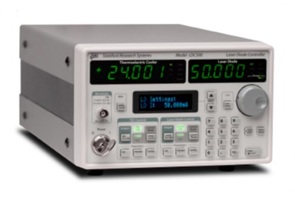
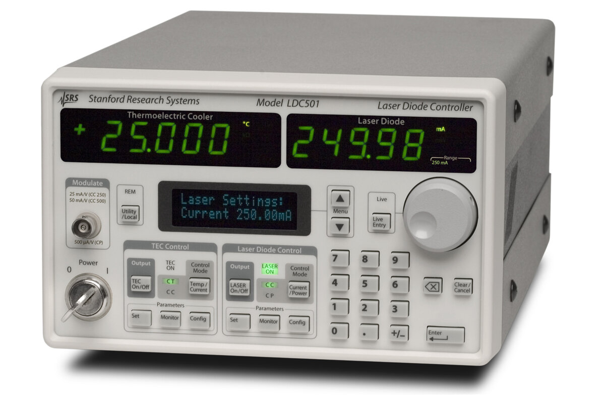
The LDC500 Series laser diode controllers control both the drive current and operating temperature of laser diodes. The LDC500, LDC501 and LDC502 provide maximum laser currents of 100 mA, 500 mA and 2 A respectively. Selectable high and low current ranges provide finer setpoint resolution and lower noise when full output capacity is not required. The laser output supports constant current and constant optical power regulation with live transfer between control modes. An integrated 36 W bipolar TEC section supports thermistors, Pt-100 and Pt-1000 RTDs, voltage-output sensors and current-output sensors.
The TEC section can operate in constant temperature or constant current mode and includes digital PID control with automatic tuning. Analogue modulation, automated scanning and a synchronisation output support laser characterisation and coordinated test sequences. Programmable current, compliance and temperature limits help protect the connected laser diode and thermal assembly. GPIB, RS-232 and Ethernet interfaces enable complete control from laboratory or production software.
Range features
A high level overview of what this range offers
- 100 mA, 500 mA and 2 A variants: Match the controller to the laser diode’s maximum current requirement.
- High and low current ranges: Obtain finer control and lower noise when operating below maximum output.
- Constant current and constant optical power modes: Regulate electrical drive current or optical output using monitor-photodiode feedback.
- Live CC and CP mode transfer: Change laser control mode without routinely switching off the output.
- Up to 1 MHz analogue modulation bandwidth: Support current modulation and dynamic laser characterisation.
- Programmable current and compliance limits: Protect the laser diode against unsuitable electrical operating conditions.
- 36 W bipolar TEC output: Control heating and cooling with up to ±4.5 A of TEC current.
- Digital PID control with automatic tuning: Configure the temperature loop for the connected thermal stage.
- Multiple temperature sensor formats: Use thermistors, Pt-100 or Pt-1000 RTDs, and common voltage- or current-output IC sensors.
- Temperature and TEC trip functions: Shut down configured outputs when temperature, current, voltage or sensor limits are reached.
- GPIB, RS-232 and Ethernet control: Integrate the instrument into automated optical test systems.
- Automated scanning and TTL synchronisation: Coordinate stepped operating-point changes with external measurement equipment.
- Independent, electrically isolated sections: Reduce unwanted interaction between the laser driver, TEC controller and control interface.
- Nine stored configurations: Recall frequently used instrument settings for repeatable tests.
Downloads
for LDC500 Laser diode controllers
What’s in this range?
All the variants in the range and a comparison of what they offer
Performance figures apply after a one-hour warm-up at 25 °C ambient unless stated otherwise.
General specifications
| Category | Specification | Value |
|---|---|---|
Operating condition | Performance specification condition | One-hour warm-up at 25 °C ambient |
Laser diode control | Operating modes | Constant current and constant optical power |
Laser current output | DC output impedance | 1 MΩ minimum |
Laser current output | Thermal drift | ±10 ppm/°C maximum |
Laser current output | Short-term stability | ±5 ppm full scale over 1 hour |
Laser current output | Long-term stability | ±15 ppm full scale over 24 hours |
Compliance voltage | Range | 0.1 to 10 V |
Compliance voltage | Resolution | 10 mV |
Compliance voltage | Accuracy | 0.2 V |
Analogue modulation | Input range | −10 to +10 V |
Analogue modulation | Input impedance | 2 kΩ typical |
Analogue modulation | Low-bandwidth CC response | DC to 10 kHz |
Analogue modulation | High-bandwidth CP response | DC to 5 kHz |
Analogue modulation | Low-bandwidth CP response | DC to 100 Hz |
Monitor photodiode | Programmable bias | 0 to 5 V |
Monitor photodiode | CP setpoint resolution | 0.1 µA |
Synchronisation output | Pulse format | Negative-going TTL pulse, 10 µs width |
Synchronisation output | Programmable delay | 0.004 to 1000 s |
TEC control | Operating modes | Constant temperature and constant current |
Temperature control | IC sensor range | −55 to +150 °C |
Temperature control | Resistive sensor temperature range | −150 to +250 °C |
Temperature control | Resistive sensor range | 10 Ω to 500 kΩ |
Temperature control | Temperature setpoint resolution | 0.001 °C |
Temperature control | Resistance setpoint resolution | 0.1 Ω |
Temperature control | Instrument temperature accuracy | ±0.01 °C, excluding sensor uncertainty |
Temperature control | Resistance setpoint accuracy | ±0.1% |
Temperature control | Thermal drift | ±0.0005 °C/°C |
Temperature control | Short-term stability | ±0.001 °C over 1 hour |
Temperature control | Long-term stability | ±0.002 °C over 24 hours |
Temperature control | Control algorithm | Digital PID |
Temperature control | Automatic tuning method | Open-loop step response |
TEC output | Current range | −4.5 to +4.5 A |
TEC output | Maximum power | 36 W |
TEC output | Current setpoint resolution | 1 mA |
TEC output | Current setpoint accuracy | ±5 mA |
TEC output | Compliance voltage | 8 V |
TEC output | Polarity | Software reversible |
TEC output | Noise and ripple | 0.1 mA rms at 1 A; 0.2 mA rms at 4 A, measured from 10 Hz to 1 MHz |
TEC output | Current limit | 0 to 4.5 A, 1 mA resolution, ±5 mA accuracy |
Temperature sensors | Thermistor excitation | 10 µA, 100 µA or 1000 µA |
Temperature sensors | Thermistors | 10 Ω to 500 kΩ |
Temperature sensors | RTDs | Pt-100, Pt-1000 and equivalents |
Temperature sensors | Voltage-output ICs | LM335 and equivalents, 1 mA bias |
Temperature sensors | Current-output ICs | AD590 and equivalents, greater than 5 V bias |
Measurement | Temperature resolution | 0.001 °C |
Measurement | Thermistor measurement | 0.1 Ω resolution; ±0.2% + 0.05 Ω accuracy with 1 mA excitation |
Measurement | TEC current | 1 mA resolution; ±5 mA accuracy |
Measurement | TEC voltage | 1 mV resolution; ±5 mV accuracy |
Remote interfaces | Communications | GPIB IEEE-488.2, RS-232 and Ethernet/TCP-IP |
Configuration storage | User configurations | Up to nine configurations in non-volatile memory |
Instrument connectors | Laser, TEC and auxiliary | DB9-F, DB15-F and BNC modulation/trigger connectors |
AC input | Power | 100 W; 100, 120, 220 or 240 V; 50 or 60 Hz |
Protection | Fuses | 4 A for 100–120 V; 2 A for 220–240 V; 5 × 20 mm fast-blow type |
Mechanical | Dimensions | 8.5 in W × 5 in H × 15 in D |
Mechanical | Weight | 15 lb |
Warranty | Coverage | One year for defects in materials and workmanship |
Variant comparison
| Specification | LDC500 | LDC501 | LDC502 |
|---|---|---|---|
High current range | 0 to 100 mA | 0 to 500 mA | 0 to 2000 mA |
Low current range | 0 to 50 mA | 0 to 250 mA | 0 to 1000 mA |
Current setpoint resolution | 1 µA | 10 µA | 100 µA |
Current accuracy | ±10 µA | ±50 µA | ±200 µA |
High-range noise density, typical | 0.7 nA/√Hz | 3.5 nA/√Hz | 12.5 nA/√Hz |
Low-range noise density, typical | 0.4 nA/√Hz | 1.8 nA/√Hz | 6.3 nA/√Hz |
Wide-band noise, high range/high bandwidth | 0.9 µA rms | 4.5 µA rms | 25 µA rms |
Wide-band noise, high range/low bandwidth | 0.6 µA rms | 1.5 µA rms | 5.0 µA rms |
Wide-band noise, low range/high bandwidth | 0.5 µA rms | 2.3 µA rms | 10 µA rms |
Wide-band noise, low range/low bandwidth | 0.3 µA rms | 1.0 µA rms | 3.5 µA rms |
Power-fail transient, maximum | 1 mA | 1 mA | 5 mA |
Current-limit resolution | 10 µA | 10 µA | 100 µA |
Current-limit accuracy | ±100 µA | ±100 µA | ±400 µA |
High-range CC modulation transfer | 10 mA/V | 50 mA/V | 200 mA/V |
Low-range CC modulation transfer | 5 mA/V | 25 mA/V | 100 mA/V |
CP modulation transfer | 500 µA/V | 500 µA/V | 1000 µA/V |
High-bandwidth CC response | DC to 1.0 MHz | DC to 1.0 MHz | DC to 0.8 MHz |
Photodiode current range | 0 to 5000 µA | 0 to 5000 µA | 0 to 10,000 µA |
Photodiode setpoint accuracy | ±3 µA | ±3 µA | ±6 µA |
Laser current display resolution | 1 µA | 10 µA | 100 µA |
Wide-band current noise is specified from 10 Hz to 1 MHz. Modulation bandwidth can vary with the connected cable, laser diode and load conditions.
FAQs
for LDC500 Laser diode controllers
Choose primarily by maximum operating current, then consider the required setpoint resolution and noise. The LDC500 provides 100 mA and 50 mA ranges with 1 µA resolution, the LDC501 provides 500 mA and 250 mA ranges with 10 µA resolution, and the LDC502 provides 2 A and 1 A ranges with 100 µA resolution. Low-range, low-bandwidth noise is 0.3, 1.0 and 3.5 µA rms respectively. Selecting the smallest variant and range that covers the operating point will generally provide finer current control. Allow sufficient headroom for modulation and operating tolerances without choosing an unnecessarily high range.
Yes, constant power mode regulates the monitor photodiode current rather than holding the electrical drive current fixed. The photodiode input covers 0 to 5000 µA on the LDC500 and LDC501, or 0 to 10,000 µA on the LDC502, with a programmable bias of 0 to 5 V. A photodiode responsivity value can be entered so that the optical setpoint is handled in milliwatts instead of raw photocurrent. The CP feedback bandwidth is DC to 5 kHz in high-bandwidth mode or DC to 100 Hz in low-bandwidth mode. This mode is appropriate when optical output stability is more important than maintaining a fixed injection current.
It is suitable when the mount’s TEC requirements remain within ±4.5 A, 36 W and approximately 8 V compliance. The controller accepts thermistors from 10 Ω to 500 kΩ, Pt-100 and Pt-1000 RTDs, LM335-type voltage sensors and AD590-type current sensors. Temperature can be programmed with 0.001 °C resolution, while the instrument contribution to setpoint accuracy is ±0.01 °C. Sensor calibration and construction remain important because sensor uncertainty can add as much as 2 °C to absolute accuracy. Check the TEC voltage-current curve, heat load, heatsink and sensor arrangement before deciding whether the available output is sufficient.
Use the ±10 V, 2 kΩ differential modulation input and select the model, current range and bandwidth setting that match the required modulation depth. High-bandwidth CC operation reaches DC to 1 MHz on the LDC500 and LDC501, or DC to 0.8 MHz on the LDC502, although cable and load characteristics can reduce the usable response. Bandwidth also falls at very low DC operating current; a typical LDC500 or LDC501 response at 2% of full scale is around 150 kHz. Ground-referenced lasers require careful management of return paths and modulation-source impedance. If an external attenuator is needed, use a balanced divider and disable the modulation input when it is not in use.
Configure the laser current limit, compliance voltage and required temperature or TEC trip conditions before enabling the output. The DB9 interlock requires a low-resistance connection between pins 1 and 2, and neither interlock pin should be connected to ground or another signal. A three-second enable delay, controlled turn-on, current clamping and shutdown functions reduce exposure to abrupt electrical events. The laser output can also be configured to switch off if the TEC stops or if an upper or lower temperature limit is crossed. External RF injection must be assessed separately because electrical stress introduced outside the controller cannot be limited by its internal protection circuits.
Yes, all principal instrument functions can be controlled through GPIB, RS-232 or Ethernet/TCP-IP. Automated scans can step the active current or photodiode setpoint by a defined increment and dwell time, making the function useful for characterisation routines. A negative-going 10 µs TTL synchronisation pulse can be generated after each step, with a programmable delay from 0.004 to 1000 seconds. Up to nine complete operating configurations can be retained in non-volatile memory and recalled when a test changes. These functions allow the controller to coordinate laser bias, thermal conditions and external measurement equipment within a repeatable sequence.
The laser diode connects through a DB9-F interface, while the TEC module and temperature sensor use a DB15-F interface. Separate sense terminals support four-wire laser voltage, TEC voltage and resistive sensor measurements, reducing errors caused by cable resistance. The TEC cable should be independently shielded from the laser diode cable because it can carry up to 4.5 A and may otherwise couple unwanted signals into the drive circuit. Some standard DB9 laser mounts can use terminated cables directly, while grounding-dependent mounts may require a flying-lead cable and application-specific wiring. Check every pin, polarity, interlock connection and ground path with a continuity meter before enabling either output.
Allow the instrument to warm up for one hour at an ambient temperature of 25 °C before relying on the stated performance figures. Laser current stability is specified at ±5 ppm full scale over one hour and ±15 ppm full scale over 24 hours, with a maximum thermal drift of ±10 ppm/°C. The lowest wide-band noise is obtained by choosing the low current range, selecting low bandwidth and disabling the modulation input when it is not required. Temperature performance also depends on the TEC assembly, sensor attachment, thermal load and PID settings. Re-tuning the temperature loop at the intended operating point can improve settling and reduce temperature-dependent behaviour.