SR400 gated photon counter
- Technology
- Photon Counters
- Partner
- Stanford Research Systems (SRS)
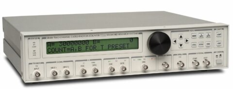
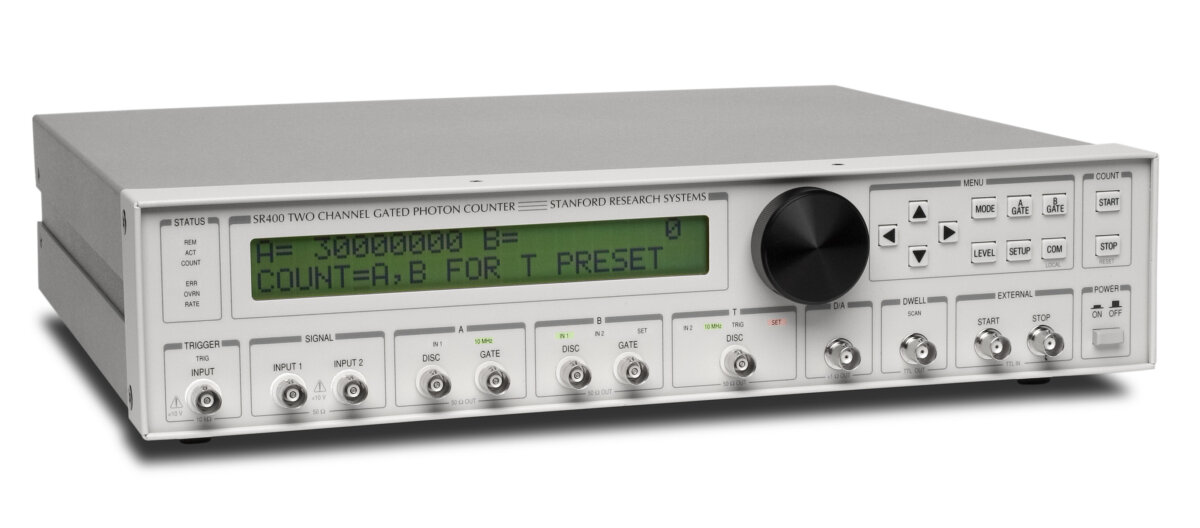
The SR400 gated photon counter is designed for engineers and researchers working with low-level optical or particle-detection signals. Two independent measurement channels allow signal, reference, background or compensation counts to be acquired within the same measurement sequence. Integrated DC to 300 MHz input amplifiers and programmable discriminators reduce the need for separate signal-conditioning and threshold modules. Each channel has an independent gate generator for continuous counting, fixed time-window measurements or scanned time-resolved acquisition.
Built-in A − B and A + B calculations support background subtraction and synchronous measurements without external arithmetic hardware. Gate and discriminator outputs provide direct timing visibility when setting thresholds and aligning measurement windows. GPIB and RS-232 interfaces, together with separate 2,000-point scan buffers for the A and B counters, support automated laboratory acquisition and instrument control.
Range features
A high level overview of what this range offers
- Two independent measurement channels: Supports simultaneous signal, reference or background counting.
- Three counters operating at up to 200 MHz: Accommodates fast pulse streams and preset timing functions.
- 5 ns pulse-pair resolution: Distinguishes closely spaced detector pulses within the counter limits.
- Independent A and B gate generators: Allows separate timing windows for signal and background measurements.
- Gate widths from 5 ns to 999.2 ms or continuous: Covers short-pulse, lifetime and continuous-source experiments.
- Programmable gate scanning: Recovers time-dependent waveforms and decay profiles across as many as 2,000 points.
- Built-in discriminators with 0.2 mV resolution: Enables controlled threshold setting for positive or negative pulses.
- DC to 300 MHz, 50 Ω signal inputs: Connects directly to compatible fast detector and preamplifier outputs.
- A − B and A + B count modes: Supports background correction and combined-channel measurements.
- NIM-level discriminator and gate outputs: Assists threshold adjustment and timing verification with external test equipment.
- Linear or logarithmic analogue output: Provides count-related signals for recorders and other analogue equipment.
- GPIB and RS-232 interfaces: Enables remote configuration and transfer of buffered count data.
Downloads
for SR400 gated photon counter
What’s in this range?
All the variants in the range and a comparison of what they offer
| Specification | Value |
|---|---|
Product type | Dual-channel gated photon counter |
Internal counters | A, B and T |
Maximum counter rate | 200 MHz for all three counters |
A and B count capacity | 10⁹ counts |
T counter preset capacity | Up to 25 hours or 9 × 10¹¹ counts, gates or triggers |
Timer accuracy | 25 ppm from 0 to 50 °C |
Count modes | A and B for T preset; A − B for T preset; A + B for T preset; A for B preset |
Signal input bandwidth | DC to 300 MHz |
Signal input impedance | 50 Ω |
Signal input linear range | ±300 mV at the input |
Signal input protection | ±5 VDC; 50 V for 1 µs |
Overload recovery | 5 ns for overloads shorter than 10 µs |
Discriminator range | −300 mV to +300 mV |
Discriminator slope | Rising or falling |
Discriminator resolution | 0.2 mV |
Input offset voltage | <1 mV |
Minimum pulse input | 10 mV |
Pulse-pair resolution | 5 ns |
Discriminator outputs | NIM levels into 50 Ω |
Inhibit input | TTL high stops counting |
Trigger input impedance | 10 kΩ |
Trigger threshold | ±2.000 VDC in 1 mV steps |
Trigger slope | Rising or falling |
Trigger input protection | 15 VDC; 100 V for 1 µs |
Gate generators | Two independent generators, AGATE and BGATE |
Gate operating modes | Continuous, fixed or scanned |
Gate insertion delay | 25 ns |
Maximum programmable gate delay | 999.2 ms |
Gate width | 5 ns to 999.2 ms or continuous |
Gate timing resolution | 0.1% or 1 ns minimum, whichever is greater |
Gate timing accuracy | 2 ns + 1% |
Gate jitter | 200 ps RMS + 100 ppm |
Maximum gate trigger rate | 1 MHz |
Gate-view outputs | NIM levels into 50 Ω |
Gate-view error | <2 ns |
Scan length | 1 to 2,000 count periods or data points |
Dwell time | 2 ms to 60 s or externally controlled |
Internal data buffer | One scan; up to 2,000 values for each A and B counter |
Display modes | Continuous or hold |
Displayed channel functions | A, B, A − B or A + B |
Front-panel display capacity | Up to 10⁹ counts |
Analogue output scaling | Linear or logarithmic at 1 V per decade |
D/A output full scale | ±10 VDC |
D/A output resolution | 12 bits; 5 mV |
D/A output current rating | 10 mA |
D/A output impedance | <1 Ω |
D/A output accuracy | 0.1% + 5 mV |
Rear-panel D/A outputs | Two, designated Port 1 and Port 2 |
Computer interfaces | GPIB and RS-232 |
Maximum RS-232 rate | 19.2 kbaud |
Dimensions | 16 × 13 × 3.5 in, W × D × H |
Weight | 10 lb |
Power consumption | 35 W |
AC input | 100, 120, 220 or 240 VAC; 50/60 Hz |
Line fuse | 1 A slow-blow fuse |
Warranty | One year for defects in materials and workmanship |
FAQs
for SR400 gated photon counter
Yes, provided the detector pulses are compatible with the electrical input limits of the SR400 gated photon counter. Its two 50 Ω inputs have DC to 300 MHz bandwidth, accept pulses within a ±300 mV linear range and can detect pulses as small as 10 mV. Each discriminator can be set between −300 mV and +300 mV in 0.2 mV steps, with rising- or falling-edge selection for either pulse polarity. A suitable fast preamplifier may be required when the detector signal is below 10 mV or cable losses reduce the available pulse amplitude. For PMT installations, a leakage path of approximately 100 kΩ to ground should be provided within the PMT base to prevent cable charging that could damage the input.
The gate width should be matched to the part of the detector response that contains the required signal while excluding as much unrelated background as practical. Each channel provides a gate width from 5 ns to 999.2 ms, with a 25 ns insertion delay and a programmable delay extending to 999.2 ms. Timing resolution is 0.1% or 1 ns minimum, while specified gate accuracy is 2 ns + 1% and jitter is 200 ps RMS + 100 ppm. For lifetime measurements, the gate can be scanned across as many as 2,000 count periods to reconstruct the temporal response. The 1 MHz maximum trigger rate must also be considered when setting the repetition rate of the experiment.
Yes, the independent A and B channels can be arranged to count signal and background windows within the same experiment. In a chopped optical measurement, one gate can be positioned during the illuminated interval while the other measures the closed or background interval. Selecting A − B then produces a background-corrected count result, while A + B is available when the two channels need to be combined. Equal gate widths should normally be used for synchronous subtraction so that both channels observe equivalent time intervals. Because the gate delays and operating modes are independently adjustable, the same approach can also support a scanned signal window with a fixed background reference.
The counter electronics accept rates up to 200 MHz and specify 5 ns pulse-pair resolution, but the complete detector chain may impose a lower practical limit. The signal inputs provide DC to 300 MHz bandwidth and require a minimum pulse amplitude of 10 mV, so pulse shape, cable bandwidth and impedance matching remain important. The separate 1 MHz specification applies to the gate trigger rate rather than the individual pulses counted inside a gate. At high PMT rates, detector recovery time, base design, gain variation and pulse pile-up can affect counting linearity before the electronic counter limit is reached. The full installation should therefore be validated over the intended count-rate range using the selected detector, base, bias voltage and preamplifier.
The instrument provides GPIB and RS-232 interfaces for remote setup, control and data transfer. A scan may contain between 1 and 2,000 count periods, with the A and B values stored in separate 2,000-point internal buffers. Dwell intervals can be programmed from 2 ms to 60 s or controlled through external start and stop inputs, allowing other instruments to be adjusted between measurements. RS-232 communication operates at up to 19.2 kbaud, while GPIB can be used where an IEEE-488 laboratory bus is already installed. Generic *IDN? queries should be avoided during National Instruments Measurement & Automation setup because they can lock the instrument; the dedicated SR400 command set should be used instead.
Continuous operation is suitable when the photon stream is not tied to a short timing event and counting should remain enabled throughout each count period. Fixed-gate operation is intended for pulsed or synchronised experiments where only a defined time window after the trigger contains useful information. The minimum 5 ns gate width can isolate short events, while widths up to 999.2 ms accommodate slower processes. Scanned-gate operation moves the timing window between successive count periods, enabling lifetime curves and other time-varying responses to be reconstructed. Chopped measurements can use separate A and B gates for illuminated and background intervals, with the resulting counts combined through A − B processing.
The instrument requires bench or rack space for an enclosure measuring 16 × 13 × 3.5 inches and weighing 10 lb. It consumes 35 W and can be configured for 100, 120, 220 or 240 VAC operation at 50/60 Hz. The voltage selector must match the available supply before power is connected, and a 1 A slow-blow fuse is specified for each supported voltage setting. A protective earth connection is required because exposed metalwork and the front-panel BNC shields are connected to chassis and mains earth. No voltage should be applied to the BNC shields or instrument outputs. PMT systems also require appropriate high-voltage procedures and a correctly designed base that prevents stored cable charge from reaching the signal input.