Low-Noise Preamplifiers
- Technology
- Pre-amplifiers
- Partner
- Stanford Research Systems (SRS)
This product range combines thirteen preamplifier models for different signal sources and measurement conditions. It includes general-purpose voltage preamplifiers, current-to-voltage amplifiers, high-impedance inputs, transformer-coupled designs and RF instruments for fast pulses. Engineers can select JFET, BJT, transimpedance or transformer input architectures according to source impedance, detector type, required noise performance and frequency range. Bench instruments provide adjustable gain, filters, bias controls, battery operation or remote interfaces where required. Compact models can be positioned close to a detector to reduce input cable capacitance and unwanted pickup.
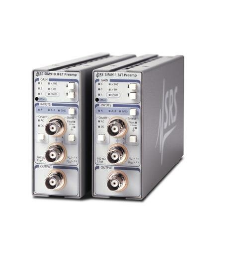
Modular SIM910, SIM911 and SIM918 versions support front-panel operation and serial control through a compatible instrumentation mainframe. Typical applications include optical detection, photomultiplier and photodiode measurements, low-temperature experiments, synchronous detection, audio engineering and general low-level signal acquisition.
Range features
A high level overview of what this range offers
- Voltage, current, RF and transformer input architectures – Match the preamplifier to the detector and source impedance.
- Voltage-noise ratings from 0.1 nV/√Hz – Support measurements from low-impedance voltage sources when the appropriate model is selected.
- Current-noise ratings down to 5 fA/√Hz – Provide options for low-current photonic and detector measurements.
- Bandwidths extending to 400 MHz – Cover low-frequency synchronous measurements and fast detector pulses.
- Fixed, selectable and programmable gain models – Accommodate dedicated experiments and adjustable measurement chains.
- Differential and single-ended input options – Support different signal references and common-mode rejection requirements.
- Floating input shields on selected models – Help interrupt unwanted ground-loop paths.
- Configurable filters, bias controls and offset functions – Enable signal conditioning before the main measurement instrument.
- Battery, mains, control-cable and modular power options – Support bench, isolated and integrated instrumentation configurations.
- RS-232, USB and SIM serial interfaces on selected models – Enable remote configuration and automated measurements.
Downloads
for Low-Noise Preamplifiers
What’s in this range?
All the variants in the range and a comparison of what they offer
Overall Range Specifications
| Specification | Range details |
|---|---|
Product scope | 13 model identifiers covering voltage, current, RF, high-impedance and transformer-coupled preamplifiers |
Frequency coverage | DC operation on selected models; maximum bandwidth of 400 MHz on the SR446 |
Voltage input noise | Model-dependent values from 0.1 nV/√Hz on the SR554 to 12 nV/√Hz at 1 kHz on the SR551 |
Current input noise | 5 fA/√Hz on the SR556 and selected SR570 settings; SIM918 values from 15 to 130 fA/√Hz depending on gain |
Voltage gain | Adjustable gains from ×1 to ×50,000; up to ×625 by cascading SR445A channels; ×100 or ×500 on the SR554 |
Current conversion | SR570 sensitivity from 1 pA/V to 1 mA/V; fixed or selectable transimpedance from 10⁶ to 10⁹ V/A on other current models |
Input impedance | From below 1 Ω DC on the SIM918 to above 1 TΩ on the SR551, depending on input architecture |
Input configurations | Single-ended, differential, virtual-null, transformer-coupled, 50 Ω and 500 Ω options depending on model |
Signal conditioning | AC/DC coupling, configurable low-pass and high-pass filters, input bias, offset-current control and autozero functions on selected models |
Interfaces | RS-232, USB or serial SIM interface on remotely controllable models |
Power arrangements | Mains, rechargeable batteries, lock-in preamplifier power connector, modular mainframe or external DC supply depending on model |
Operating temperature | Generally 0 °C to 40 °C; the SR446 operation manual specifies +5 °C to +40 °C |
Warranty | One year for defects in materials and workmanship |
Model Comparison
| Specification | SR560 | SR570 | SR445A | SR446 | SR550 | SR551 | SR552 | SR554 | SR555 | SR556 | SIM910 | SIM911 | SIM918 |
|---|---|---|---|---|---|---|---|---|---|---|---|---|---|
Preamplifier type | Voltage | Current | Four-channel RF voltage | Programmable RF voltage | FET voltage | High-impedance voltage | BJT voltage | Transformer-coupled voltage | Fixed-gain current | Fixed-gain current | JFET voltage module | BJT voltage module | Precision current module |
Input noise | 4 nV/√Hz at 1 kHz | Sensitivity-dependent; down to 5 fA/√Hz | 6.4 nV/√Hz | 3.3 nV/√Hz at 1 MHz | 3.6 nV/√Hz at 1 kHz | 12 nV/√Hz and 0.6 fA/√Hz at 1 kHz | 1.4 nV/√Hz at 1 kHz | 0.1 nV/√Hz | 42 fA/√Hz at 1 kHz | 5 fA/√Hz at 1 kHz | 4 nV/√Hz at 1 kHz | 1.8 nV/√Hz at 1 kHz | 130, 42 or 15 fA/√Hz at 100 Hz |
Gain or sensitivity | ×1 to ×50,000 | 1 pA/V to 1 mA/V | ×5 per channel; up to ×625 cascaded | ×1 to ×100 in 2 dB steps | ×1, ×2, ×5 or ×10 | Fixed ×10 | ×10, ×20, ×50 or ×100 | ×100 or ×500 | 10⁷ V/A | 10⁹ V/A | ×1 to ×100 | ×1 to ×100 | 10⁶, 10⁷ or 10⁸ V/A |
Frequency behaviour | 1.2 MHz typical −3 dB bandwidth | Up to 1 MHz; setting-dependent | DC to 350 MHz | DC to 400 MHz | 16 mHz AC-coupling corner; gain accuracy specified to 100 kHz | DC to 1 MHz | 16 mHz AC-coupling corner; gain accuracy specified to 100 kHz | 0.1 Hz to 40 kHz maximum response | DC to 120 kHz | DC to 3 kHz | DC to 1 MHz rated; 1.9 MHz typical −3 dB | DC to 1 MHz | 22, 12 or 4 kHz depending on gain |
Input characteristics | 100 MΩ + 25 pF; single-ended or differential | Virtual null or ±5 V bias; impedance varies from 1 Ω to 1 MΩ | 50 Ω; channel 1 selectable to approximately 500 Ω | 50 Ω or 500 Ω; AC, DC or grounded | 100 MΩ + 25 pF | Greater than 1 TΩ | 100 kΩ + 25 pF | Recommended source impedance from 0.05 Ω to 1 kΩ | 50 Ω, 16 pF | 50 Ω, 12 pF | 100 MΩ in parallel with 35 pF | 100 kΩ in parallel with 35 pF | Below 1 Ω DC, 18 pF |
Control and power | RS-232; mains or internal battery | RS-232; mains or internal battery | Manual control; mains | USB; mains | Control cable or external DC | Control cable or external ±20 VDC | Control cable or external DC | Passive at ×100; control cable or external ±20 VDC at ×500 | Control cable or external DC | Control cable or external DC | SIM serial interface; mainframe or external DC | SIM serial interface; mainframe or external DC | SIM serial interface; mainframe or external DC |
FAQs
for Low-Noise Preamplifiers
Choose the input architecture from the detector output and source impedance before comparing gain or bandwidth. Voltage models suit sensors that already generate a measurable voltage, while current preamplifiers convert photodiode, ionisation or other detector currents into a voltage through a stated transimpedance. The SR551 provides an input impedance above 1 TΩ for sources that must not be resistively loaded, whereas the SR554 is intended for source impedances from 0.05 Ω to 1 kΩ and provides transformer isolation. For fast photomultiplier or photodiode pulses, the 350 MHz SR445A and 400 MHz SR446 provide 50 Ω signal paths. This first architectural choice prevents unsuitable loading and avoids selecting a noise figure that is irrelevant to the actual source.
The voltage-noise figure should be considered together with input impedance and input-current noise. The SR550 and SIM910 use FET or JFET inputs with 100 MΩ input impedance, making them suitable for higher-impedance voltage sources than the BJT alternatives. The SR552 and SIM911 reduce voltage noise to 1.4 and 1.8 nV/√Hz respectively, but their 100 kΩ input impedance can load a high-resistance source. The SR551 extends input impedance beyond 1 TΩ when resistive loading must be kept very low, although its voltage noise is 12 nV/√Hz at 1 kHz. For low-impedance sources between 0.05 Ω and 1 kΩ, the SR554 provides a different approach with 0.1 nV/√Hz transformer input noise.
The SR445A and SR446 are the primary RF choices for fast detector pulses. The SR445A provides four DC-coupled channels with 350 MHz bandwidth, 1 ns rise and fall time, and gain of ×5 per channel; cascading all four produces a nominal gain of ×625. The SR446 is a single-channel 400 MHz instrument with 21 programmable gains from ×1 to ×100, selectable bandwidth limits and complementary outputs. Both are designed around 50 Ω signal paths, although each provides a 500 Ω input option for selected current- or charge-output arrangements. Correct coaxial termination remains important because an unterminated RF cable can alter amplitude, introduce reflections or affect amplifier stability.
The SR560 is suited to a stand-alone bench setup requiring wide gain adjustment, configurable analogue filtering and battery operation. It provides gain from ×1 to ×50,000, two configurable filters with cutoff settings from 0.03 Hz to 1 MHz, differential or single-ended inputs and up to 15 hours of battery operation. The SIM910 and SIM911 are modular alternatives with gain from ×1 to ×100, DC-to-1 MHz operation and serial control through a compatible mainframe. The SIM910 provides a 100 MΩ JFET input, while the SIM911 provides lower voltage noise with a 100 kΩ BJT input. Selection therefore depends on required gain range, source impedance, filtering, physical integration and whether line-independent operation is necessary.
The SR570 is the flexible choice when one experiment must cover a wide range of current levels and bandwidths. Its sensitivity extends from 1 pA/V to 1 mA/V, with configurable filters, adjustable input offset current, ±5 V bias and operating modes that trade noise, bandwidth and drift. The SR555 and SR556 are compact fixed-gain alternatives: the SR555 provides 10⁷ V/A with 120 kHz bandwidth, while the SR556 provides 10⁹ V/A with 3 kHz bandwidth and 5 fA/√Hz input noise. The SIM918 provides selectable gains from 10⁶ to 10⁸ V/A, gain-dependent bandwidth from 22 to 4 kHz and an autozero function that holds input offset below 10 µV. The appropriate choice depends on whether the design requires broad adjustability, fixed conversion gain, low offset or modular remote control.
Place the preamplifier close to the detector when practical, particularly for current sources whose cable capacitance can increase noise and restrict bandwidth. RF models should use correctly terminated 50 Ω coaxial paths, while the 500 Ω settings should only be used when their higher input impedance suits the detector and cabling arrangement. The SR555 and SR556 provide balanced differential outputs, so equal-length output cables and a differential receiving input are preferable. Floating inputs and shields on the SR560, SIM910 and SIM911 can help control ground loops, provided common-mode limits are respected. Where galvanic separation is required, the SR554 provides greater than 40 dB isolation from DC to 500 MHz and allows its transformer primary to float to ±100 VDC.
The SR560 and SR570 provide receive-only RS-232 control at 9600 baud, allowing instrument settings to be changed remotely while keeping the interface isolated from the analogue circuitry. The SR446 uses USB with serial-port emulation and supports remote configuration of input coupling, impedance, gain and output filtering. The SIM910, SIM911 and SIM918 use a serial interface through the modular instrumentation platform and permit settings to be queried as well as changed. The SR445A, SR550, SR551, SR552, SR554, SR555 and SR556 are primarily configured through hardware controls or fixed operating arrangements. Automated-system designers should therefore confirm whether they need remote setting changes, status readback or only a fixed analogue front end.
Higher current-to-voltage conversion generally reduces available bandwidth, so both values must be selected together. On the SR570, a sensitivity of 10⁻³ A/V supports bandwidth up to 1 MHz, while the 10⁻¹² A/V setting is limited to 10 Hz. The SIM918 provides 22 kHz bandwidth at 10⁶ V/A, 12 kHz at 10⁷ V/A and 4 kHz at 10⁸ V/A. The fixed-gain SR555 and SR556 illustrate the same trade-off, offering 120 kHz at 10⁷ V/A and 3 kHz at 10⁹ V/A respectively. In practice, choose enough transimpedance to place the signal above downstream noise, then limit the measurement bandwidth to the part of the spectrum containing useful information.