LC & Discrete Bandpass Filters
- Technology
- RF Filters
- Partner
- Sangshin
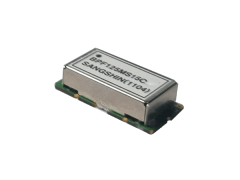
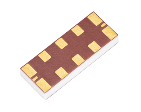
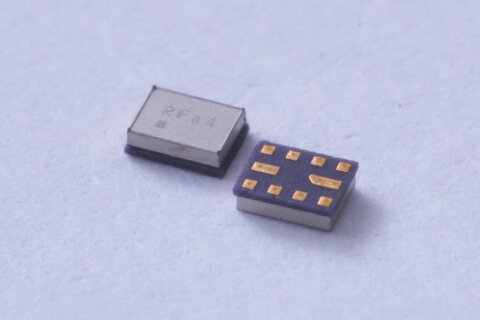
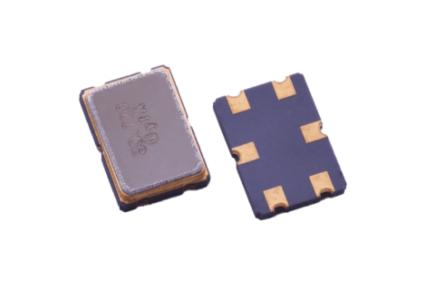
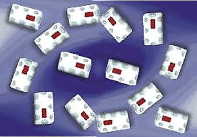
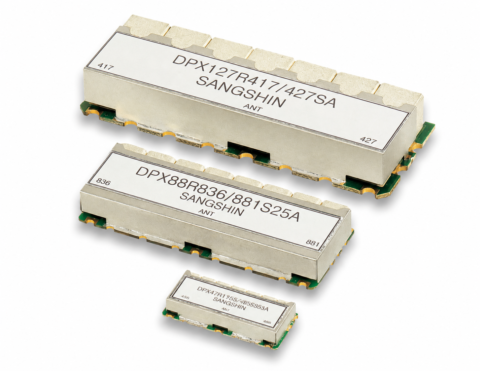
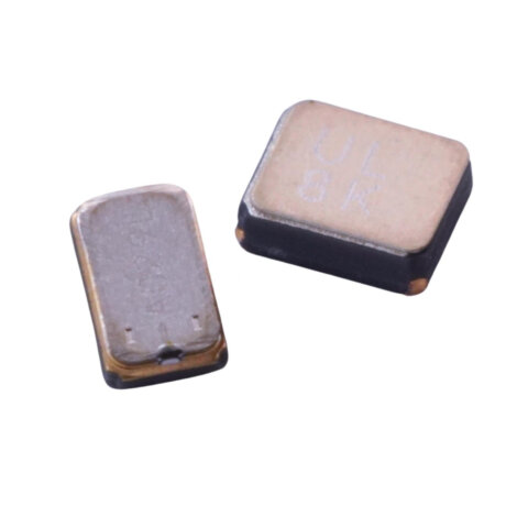
The LC and discrete bandpass filter range comprises twelve single-path RF filter variants. It includes five discrete designs and seven LC designs, with listed centre frequencies extending from 10 MHz to 1700 MHz. The available models cover both narrow and wide frequency ranges, allowing engineers to compare components against specific passband requirements. Depending on the selected frequency plan, these filters can support RF filtering duties in mobile communications, GPS, WLAN, RFID, Wi-Fi and related telecommunications equipment. Selection data includes start, centre and stop frequencies, together with insertion loss, return loss, ripple and attenuation values. Mechanical dimensions are provided for every model to support early PCB, assembly and enclosure planning. Impedance, power handling, mounting configuration, operating temperature and environmental ratings require separate confirmation before final design approval.
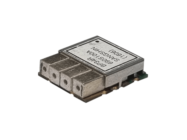
The series brings together twelve single-path RF bandpass filters using LC and discrete implementations. The range spans centre frequencies from 10 MHz to 1700 MHz and includes options suited to narrow or wide passband requirements.
Published selection data helps engineers compare models by passband limits, insertion loss, return loss, ripple, attenuation points and package dimensions. Applications may include mobile communications, GPS, WLAN, RFID, Wi‑Fi and related telecommunications equipment, subject to full design verification.
Range features
A high level overview of what this range offers
- Twelve BPF variants – Provides a choice of electrical and mechanical configurations.
- LC and discrete technologies – Supports selection by implementation type and frequency requirement.
- Single frequency path – Suitable for individual RF filtering channels.
- Centre frequencies from 10 to 1700 MHz – Covers a broad selection of RF frequency plans.
- Defined start and stop frequencies – Helps engineers compare the listed passband limits.
- Maximum insertion loss from 1.65 to 8 dB – Enables direct comparison of in-band signal loss.
- Minimum return loss from 10 to 18 dB – Provides a defined matching criterion for component selection.
- Specified attenuation points – Supports assessment of rejection at the listed out-of-band frequencies.
- Dimensions for every model – Assists with PCB layout and mechanical integration.
- Selected frequency-band identifiers – Simplifies initial filtering of models for recognised band plans.
What’s in this range?
All the variants in the range and a comparison of what they offer
| Part No. | Classification | Normalised Technology | Band | Frequency Paths | Start Freq. [MHz] | Center Freq. [MHz] | Stop Freq. [MHz] | Insertion Loss [dB/max.] | Return Loss [dB/min.] | Ripple [dB/max.] | Attenuation [dB/min.] | Dimensions (L × W × H) [mm] |
|---|---|---|---|---|---|---|---|---|---|---|---|---|
BP34R748S100A | Discrete | Discrete | 13 28 67 83 | 1 | 698 | 748 | 798 | 2 | 15 | 1.3 | 48 @ 880 ~ 1100 | 15.4 × 13 × 4.5 |
BP45R1387S625A | Discrete | Discrete | 1 | 1075 | 1387.5 | 1700 | 2 | 15 | 1.2 | 50 @ 2000 | 18 × 22.35 × 5.5 | |
BP46R1300S850A | Discrete | Discrete | 1 | 875 | 1300 | 1725 | 3 | 10 | 1.5 | 30 @ 1865 ~ 2300 | 18.5 × 26.35 × 5 | |
BP63R1575S10A | Discrete | Discrete | L1 | 1 | 1570 | 1575 | 1580 | 1.65 | 15 | 1 | 22 @ 1625 | 12 × 19 × 7 |
BP65R422S06B | Discrete | Discrete | 87 | 1 | 419.5 | 422.5 | 425.5 | 3.8 | 14 | 1 | 3 @ 417.5 | 30 × 32 × 7 |
BPF10MH05A | LC | LC | 1 | 7.5 | 10 | 12.5 | 2.4 | 15 | 1 | 10 @ 5 20 @ 20 ~ 100 | 31 × 60 × 15 | |
BPF1450MS1200A | LC | LC | 50 74 75 92 94 | 1 | 850 | 1450 | 2050 | 3.2 | 12 | 2.2 | 40 @ 700 35 @ 2200 | 15 × 47 × 6.3 |
BPF1700MS1500A | LC | LC | 1 | 950 | 1700 | 2450 | 3.2 | 10 | 15 @ 2650 ~ 2750 | 12 × 23 × 8 | ||
BPF307MS100C | LC | LC | 1 | 257.2 | 307.2 | 357.2 | 3.5 | 10 | 1.5 | 32 @ 233.4 & 381 | 12.5 × 25.5 × 6.8 | |
BPF307MS38A | LC | LC | 1 | 288.16 | 307.2 | 326.28 | 3.5 | 13 | 2 | 10 @ 276.12 | 18 × 31 × 7.3 | |
BPF70MS03B | LC | LC | 1 | 69 | 70 | 71 | 8 | 13 | 0.5 | 40 @ 78 ~ 400 | 12 × 35 × 7 | |
BPF82MS35B | LC | LC | 1 | 63 | 82.5 | 102 | 2.5 | 18 | 1 | 20 @ 110 | 12.5 × 25.5 × 6.8 |
FAQs
for LC & Discrete Bandpass Filters
Across the twelve listed variants, start frequencies extend from 7.5 MHz to 1570 MHz, centre frequencies range from 10 MHz to 1700 MHz, and stop frequencies extend from 12.5 MHz to 2450 MHz. Engineers should select a model using its individual start, centre and stop frequency values rather than the overall range limits.
The range contains five discrete bandpass filters and seven LC bandpass filters. All twelve models are specified with one frequency path.
BP63R1575S10A has the lowest listed maximum insertion loss at 1.65 dB. It operates from 1570 to 1580 MHz with a centre frequency of 1575 MHz.
BP63R1575S10A is identified for the L1 band and has a centre frequency of 1575 MHz. Its listed passband extends from 1570 to 1580 MHz, with a minimum return loss of 15 dB and maximum ripple of 1 dB.
Two LC models have a centre frequency of 307.2 MHz. BPF307MS100C covers 257.2 to 357.2 MHz, while BPF307MS38A covers the narrower range of 288.16 to 326.28 MHz.
BPF82MS35B has the highest listed minimum return loss at 18 dB. This LC filter has a centre frequency of 82.5 MHz and operates between 63 and 102 MHz.
Each attenuation value applies only at the frequency or frequency range stated for that model. These figures should not be treated as broadband rejection values outside the specified test points.
No. Dimensions vary from compact formats such as 12 × 19 × 7 mm to larger formats such as 31 × 60 × 15 mm. The selected model’s complete mounting and termination details should be confirmed before PCB layout is finalised.
System designers should confirm nominal impedance, power handling, group delay, mounting arrangement, terminal configuration, operating temperature, storage temperature and environmental requirements. These parameters are not defined in the technical selection table.