RF Combiners
- Technology
- RF Filters
- Partner
- Sangshin
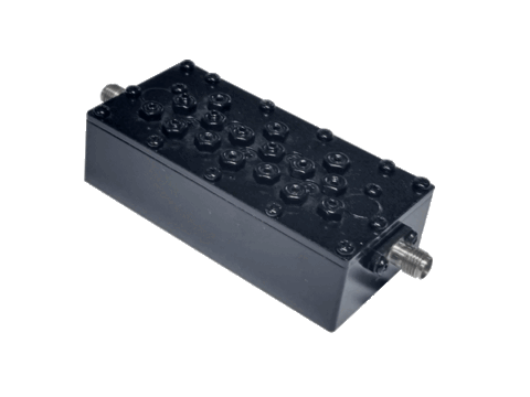
The SEHC Series is a family of multi-band RF combiners designed for communication systems that need several frequency paths within one RF assembly. The range includes two-, three-, four-, five-, six- and eight-path configurations. Across the available models, operating passbands extend from 380 MHz to 5850 MHz. Selected variants combine GPS and Wi-Fi frequencies, while another configuration adds RFID and LoRa paths. Other models cover cellular frequency allocations and paired uplink and downlink ranges. Electrical selection data includes insertion loss, return loss, ripple and attenuation under defined frequency conditions. Engineers can also compare enclosure dimensions when assessing installation space and system integration requirements.
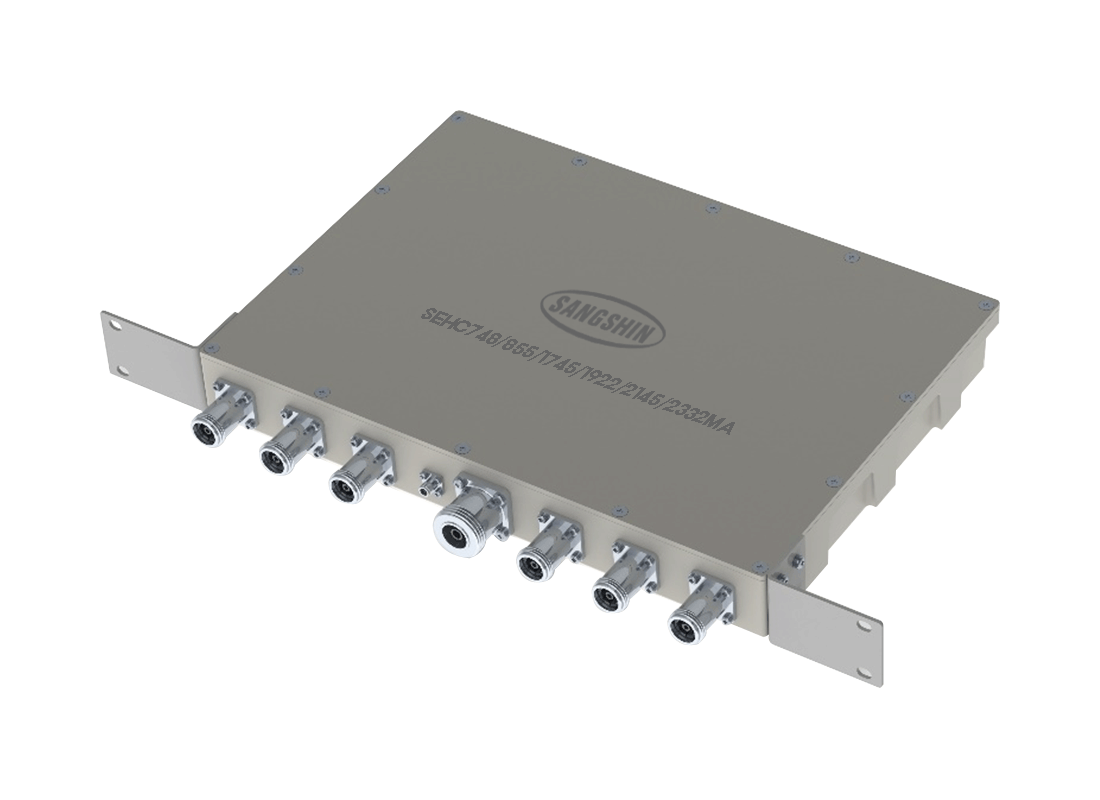
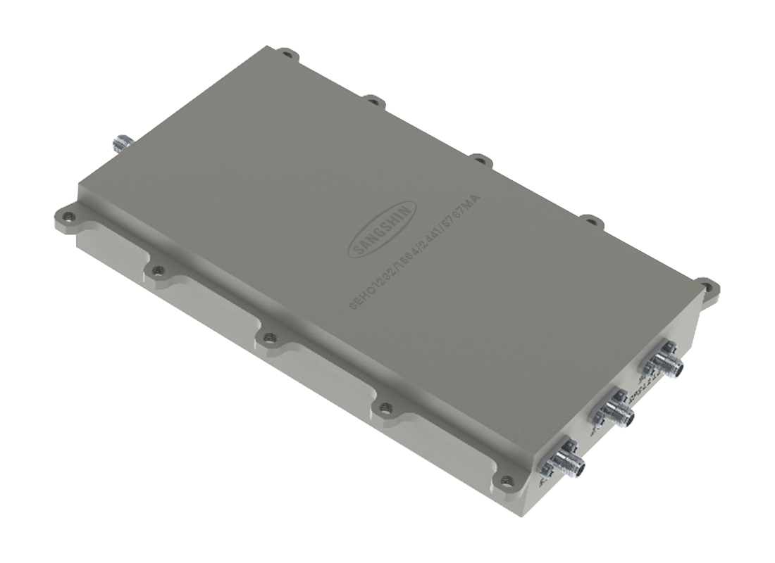
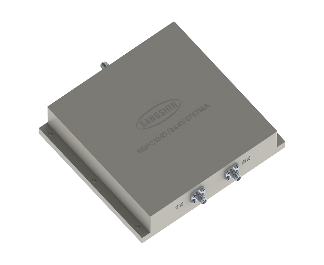
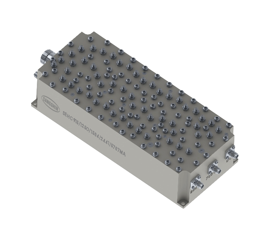
The SEHC Series Multi-band RF Combiners are intended for RF systems that need multiple defined frequency paths combined within one assembly. Available models cover a broad mix of cellular and wireless applications, including GPS, Wi-Fi, RFID and LoRa, with model-specific path counts, passbands and electrical performance.
Across the range, engineers can select from compact low-path-count units through to more complex multi-band configurations, while also comparing insertion loss, return loss, attenuation and enclosure size for integration into the target system.
Range features
A high level overview of what this range offers
- Two to eight RF paths – Supports systems that need to combine several allocated frequency ranges.
- Passbands from 380 MHz to 5850 MHz – Covers a broad selection of cellular and wireless communication frequencies.
- Maximum insertion loss from 0.3 dB to 1.8 dB – Helps engineers account for combiner losses within the RF link budget.
- Minimum return loss from 15 dB to 20 dB – Provides defined input-matching criteria for model selection.
- Model-specific attenuation from 10 dB to 90 dB – Supports rejection and isolation planning between frequency paths.
- GPS and Wi-Fi configurations – Allows satellite-navigation and wireless-network bands to be combined in one assembly.
- RFID and LoRa option – Provides additional paths for connected-device and low-power wireless applications.
- Multiple enclosure sizes – Enables mechanical selection according to the available installation space.
What’s in this range?
All the variants in the range and a comparison of what they offer
| Part No. | Classification | Band | Frequency Paths | Start Freq. [MHz] | Center Freq. [MHz] | Stop Freq. [MHz] | Insertion Loss [dB/max.] | Return Loss [dB/min.] | Ripple [dB/max.] | Attenuation [dB/min.] | Dimensions (L × W × H) [mm] |
|---|---|---|---|---|---|---|---|---|---|---|---|
SEHC1232/1584/2441/5787MA | Combiner | GPS | 4 | 1164 | 1232 | 1300 | 0.5 | 15 | 0.5 | 10 @ 1114MHz 10 @ 1350MHz | 167 × 184 × 36 |
SEHC1387/2441/5787MA | Combiner | GPS | 3 | 1164 | 1387 | 1610 | 0.5 | 15 | 0.5 | 15 @ 2400~2483.5MHz | 53.5 × 80.5 × 29 |
SEHC1945/2135/1975/2165MA | Combiner | 1 | 4 | 1940 | 1945 | 1950 | 0.5 | 20 | 30 @ Each band | 165 × 272 × 110 | |
SEHC670/1795/2060/2595MA | Combiner | 3 | 4 | 380 | 670 | 960 | 0.3 | 18 | 50 @ Each band | 216 × 230 × 52 | |
SEHC707/782/742/833/878/1882/ 1962/1742/2132MA | Combiner | 85 13 | 8 | 777 | 782 | 787 | 1.8 | 15 | 1.2 | 75~90 @ Each band | 220 × 230 × 100 |
SEHC748/855/1745/1922/2145/2332MA | Combiner | 28 | 6 | 698 | 748 | 798 | 0.5 | 20 | 0.5 | 25 @ 2800~5380MHz | 244 × 482.6 × 44 |
SEHC754/836/1925/1742/2132MA | Combiner | 44 | 5 | 698 | 754 | 806 | 0.5 | 20 | 0.4 | 50 @ Each band | 177 × 211 × 57 |
SEHC826/920MA | Combiner | 8 | 2 | 790 | 826 | 862 | 0.3 | 18 | 50 @ 880~960MHz | 270 × 372 × 75 | |
SEHC844/889/1775/1867/1925/2115MA | Combiner | 5 | 6 | 839 | 844 | 849 | 1.7 | 20 | 1.5 |
| 180 × 194 × 95 |
SEHC915/1250/1584/2441/5787MA | Combiner | RFID | 5 | 902 | 915 | 928 | 0.5 | 15 | 0.5 | 50 @ 1200~1300MHz | 167 × 184 × 36 |
FAQs
for RF Combiners
Across the complete range, the listed passbands extend from 380 MHz to 5850 MHz. Each part number has its own combination of start, centre and stop frequencies, so selection should be based on the required path allocation rather than the overall range alone.
The range includes configurations with two, three, four, five, six and eight paths. The SEHC826/920MA is a two-path model, while the SEHC707/782/742/833/878/1882/1962/1742/2132MA is listed as an eight-path model.
The SEHC1232/1584/2441/5787MA and SEHC1387/2441/5787MA include GPS and Wi-Fi frequency references. The SEHC915/1250/1584/2441/5787MA also covers GPS and Wi-Fi alongside RFID and LoRa paths.
The SEHC915/1250/1584/2441/5787MA is the five-path configuration identified for RFID, LoRa, GPS and Wi-Fi applications. Its listed passbands are 902–928 MHz, 1200–1300 MHz, 1559–1610 MHz, 2400–2483.5 MHz and 5725–5850 MHz.
Maximum insertion-loss values range from 0.3 dB to 1.8 dB, depending on the selected model and frequency path. Models such as the SEHC670/1795/2060/2595MA and SEHC826/920MA are listed with a maximum value of 0.3 dB, while some multi-path variants have different values for individual bands.
Attenuation is defined at specific frequencies, across particular rejection ranges or separately for each band. Engineers should compare the stated attenuation condition with the actual interferer frequency and required isolation, rather than treating it as a broadband value.
Listed lengths range from 53.5 mm to 270 mm, widths from 80.5 mm to 482.6 mm and heights from 29 mm to 110 mm. The enclosure dimensions vary independently of path count and should be checked for the selected part number.
Connector configuration, characteristic impedance, power handling, operating temperature, environmental sealing and mounting details are not defined in the specification table. These parameters should be confirmed for the selected part before completing the RF and mechanical design.