FT12MWNR 650 nm DC-12 MBd 50 m RedLink® POF Tilted Transmitter
- Technology
- Plastic Optical Fibre (POF) components
- Partner
- Firecomms
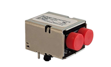
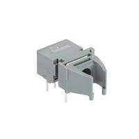
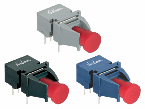
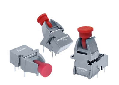
The FT12MWNR POF fibre-optic transmitter is the 30° tilted package in the FT12MxNR product family. It combines a 150 µm aperture RCLED with visible red emission centred at 650 nm. The device is intended for automation, industrial control, low-speed serial communication and voltage-isolated data links. Example interfaces and protocols include RS232, RS485, CAN bus, Modbus, Profibus and Sercos. Its non-conducting connector housing accepts Versatile Link-style fibre plugs and is suitable for 1 mm POF and 200 µm PCS/HCF fibre. Drive current can be adjusted through an external series resistor to balance coupled optical power and current consumption for the required link distance. Operation is specified from -40 °C to +85 °C, allowing the transmitter to be considered for equipment exposed to extended industrial temperatures.
Range features
A high level overview of what this range offers
- 650 nm RCLED output: Provides visible red optical transmission for POF and PCS/HCF links.
- DC-to-12 MBd data rate: Supports DC-coupled and low-speed serial communication.
- Up to 50 m over step-index POF: Accommodates industrial links subject to installation conditions.
- Up to 300 m with 200 µm PCS/HCF fibre: Provides an option for longer optical connections.
- Adjustable drive current: Allows optical output and current consumption to be balanced for the link budget.
- 30° tilted connector: Provides an angled fibre-entry orientation for PCB integration.
- -40 °C to +85 °C operating range: Supports use across extended industrial temperatures.
- 150 µm aperture and 0.5 numerical aperture: Supports optical coupling into the specified fibre types.
- -4 ns to +8 ns pulse-width distortion: Provides a defined range for system timing analysis.
- Versatile Link-style compatibility: Supports integration with the corresponding connector and cable form factor.
- UL 94 V-0 non-conducting housing: Provides a flame-retardant plastic connector enclosure.
- LED Class 1 and RoHS compliance: Supports eye-safety and restricted-substance requirements at component level.
Downloads
for FT12MWNR 650 nm DC-12 MBd 50 m RedLink® POF Tilted Transmitter
FT12MxNR 650 nm DC–12 MBd RedLink® Fibre-Optic Transmitter Preliminary Datasheet, revision P1
DownloadWhat’s in this range?
All the variants in the range and a comparison of what they offer
Electrical, optical and absolute-maximum specifications
| Category | Parameter | Symbol | Minimum | Typical | Maximum | Unit | Test condition or note |
|---|---|---|---|---|---|---|---|
Absolute maximum | Storage temperature | Tstg | -40 | — | +85 | °C | Damage limit |
Absolute maximum | Soldering temperature | Tsld | — | — | +260 | °C | 10 seconds, one time only, at least 2.2 mm from the lead root |
Absolute maximum | Transmitter reverse input voltage | VBR | — | — | -10 | V | Damage limit |
Absolute maximum | Transmitter forward input current | IFDC | — | — | 80 | mA | Damage limit |
Absolute maximum | Peak forward input current | IFPK | — | — | 1000 | mA | Subject to pulse restrictions |
Absolute maximum | Average forward input current | IFAVG | — | — | 60 | mA | Damage limit |
Environmental | Operating temperature | T | -40 | — | +85 | °C | Full drive-current range |
Optical | Coupled output power into 1 mm POF | Po | -7.2 | -3.5 | +1.3 | dBm | IFDC = 60 mA |
Optical | Coupled output power into 1 mm POF | Po | -16.8 | -9.0 | -0.7 | dBm | IFDC = 20 mA |
Optical | Coupled output power into 200 µm PCS | Po | -17.3 | -12.5 | -7.2 | dBm | IFDC = 60 mA |
Optical | Emission wavelength, centroid | λc | 635 | 650 | 665 | nm | IFDC = 30 mA |
Optical | Spectral width, RMS | λRMS | — | 11 | 16 | nm | IFDC = 30 mA |
Electrical | Forward voltage | VF | 1.8 | 2.1 | 2.65 | V | IFDC = 60 mA |
Electrical | Forward-voltage temperature coefficient | ΔVF/ΔT | — | -3.3 | — | mV/°C | IFDC = 60 mA |
Electrical | Reverse input breakdown voltage | VBR | 10 | — | — | V | IFDC = -1 µA |
Electrical | Diode capacitance | Co | — | 11 | — | pF | V = 0 V |
Optical | Transmitter numerical aperture | NA | — | 0.5 | — | — | IFDC = 60 mA |
Data | Data rate | — | DC | — | 12 | MBd | Minimum UI 83 ns; maximum f 6 MHz |
Timing | Optical rise time, 20% to 80% | tr | — | 6 | 13 | ns | IFAVG = 30 mA |
Timing | Optical fall time, 80% to 20% | tf | — | 8 | 11 | ns | IFAVG = 30 mA |
Timing | Low-to-high propagation delay, electrical to optical | tPropDly_LH | 20 | 23 | 30 | ns | IFAVG = 30 mA |
Timing | High-to-low propagation delay, electrical to optical | tPropDly_HL | 18 | 25 | 36 | ns | IFAVG = 30 mA |
Timing | Pulse-width distortion | PWD | -4 | 2 | 8 | ns | IFAVG = 30 mA |
Absolute-maximum ratings are damage thresholds rather than recommended operating settings. For peak forward current above 60 mA, pulse width must remain at or below 1 µs and average forward current must not exceed 60 mA; the specified pulsed condition covers a 60 mA to 90 mA peak range. POF optical power is measured through 0.5 m of 1 mm, 0.5 NA POF, while PCS power is measured through 0.5 m of 200 µm PCS. Timing values are measured through 50 cm of 0.5 NA POF using the specified inverting application circuit.
Product variant comparison
| Specification | FT12MHNR | FT12MVNR | FT12MWNR |
|---|---|---|---|
Package orientation | Horizontal | Vertical | 30° tilted |
Signalling option | Non-inverting TTL | Non-inverting TTL | Non-inverting TTL |
Maximum data rate | 12 MBd | 12 MBd | 12 MBd |
Pin assignment
| Pin | Name | Symbol |
|---|---|---|
1 | RCLED anode | TD+ |
2 | RCLED cathode | TD- |
3 | Not connected | N.C. |
4 | Not connected | N.C. |
5 | Retaining pin | GND |
8 | Retaining pin | GND |
Pins 5 and 8 are provided for mounting and retention and should be connected to ground.
Regulatory compliance
| Parameter | Symbol | Standard | Level |
|---|---|---|---|
Human Body Model contact electrostatic discharge | HBM | MIL-STD-883 | Level 2, 4 kV |
Radiated emissions immunity | V m⁻¹ | IEC 61000-4-3 | 15 V m⁻¹ |
Moisture-sensitivity storage classification | MSL | J-STD-020 | Level 3, one-week floor life |
Restriction of hazardous substances | RoHS | Directive 2011/65/EU | Certified compliant |
Eye safety | — | IEC 60825-1 | LED Class 1 |
Packing comparison
| Packing specification | FT12MHNR horizontal | FT12MVNR vertical | FT12MWNR tilted |
|---|---|---|---|
Components per tube | 40 | 40 | 40 |
Tube length | 515 mm | 515 mm | 515 mm |
Tube height | 16.2 mm | 20.7 mm | 21 mm |
Tube depth | 26.9 mm | 30.6 mm | 27.1 mm |
Tubes per bag | 5 | 5 | 5 |
Bags per inner carton | 1 | 1 | 1 |
Inner carton length | 630 mm | 630 mm | 630 mm |
Inner carton width | 70 mm | 70 mm | 70 mm |
Inner carton height | 105 mm | 105 mm | 105 mm |
Complete inner-carton weight | 0.77 kg | 0.92 kg | 0.92 kg |
Components per inner carton | 200 | 200 | 200 |
Inner cartons per outer carton | 10 | 10 | 10 |
Outer carton length | 650 mm | 650 mm | 650 mm |
Outer carton width | 235 mm | 235 mm | 235 mm |
Outer carton height | 376 mm | 376 mm | 376 mm |
Complete outer-carton weight | 8.13 kg | 9.60 kg | 9.60 kg |
Components per outer carton | 2,000 | 2,000 | 2,000 |
FAQs
for FT12MWNR 650 nm DC-12 MBd 50 m RedLink® POF Tilted Transmitter
Yes, the FT12MWNR is specified for distances up to 50 m using step-index POF, with the qualification that achievable distance depends on installation conditions. Its signalling range is DC to 12 MBd, with a minimum unit interval of 83 ns and a maximum stated frequency of 6 MHz. At 60 mA drive current, coupled optical power into 1 mm POF ranges from -7.2 to +1.3 dBm, while the 20 mA condition ranges from -16.8 to -0.7 dBm. Connector loss, fibre attenuation, bends and receiver sensitivity must therefore be included in the link budget. Worst-case power and timing should be validated across -40 °C to +85 °C rather than treating 50 m as an unconditional distance.
For a link of up to 50 m, 1 mm step-index POF is the stated fibre option, whereas 200 µm PCS/HCF is listed for distances up to 300 m, subject to installation conditions. Coupled optical power is characterised differently for the two fibres: at 60 mA, POF output ranges from -7.2 to +1.3 dBm, while 200 µm PCS output ranges from -17.3 to -7.2 dBm. These figures use different coupling arrangements and should not be compared as though the launch conditions were identical. POF can support straightforward routing in industrial equipment, while PCS/HCF provides a longer stated reach. Final selection should account for fibre loss, connector loss, bend radius, receiver sensitivity and environmental margin.
Drive current should be chosen from the required optical link budget rather than set automatically to the highest permitted value. In the recommended 5 V circuit, a 47 Ω series resistor produces approximately 60 mA, and selecting a higher resistance reduces the drive current. At 60 mA, the 1 mm POF coupled output range is -7.2 to +1.3 dBm; at 20 mA, it is -16.8 to -0.7 dBm. Forward voltage at 60 mA ranges from 1.8 to 2.65 V, so the driver and resistor network must accommodate device and temperature variation. The 80 mA DC, 60 mA average and 1000 mA peak figures are absolute damage limits, not normal operating targets. Pulsed operation above 60 mA must also satisfy the stated pulse-width and average-current restrictions.
The timing budget should include propagation delay, transition time and pulse-width distortion rather than relying only on the 12 MBd rating. Optical rise time is typically 6 ns and no more than 13 ns, while fall time is typically 8 ns and no more than 11 ns under the stated test conditions. Low-to-high propagation delay ranges from 20 to 30 ns, and high-to-low delay ranges from 18 to 36 ns. Pulse-width distortion spans -4 to +8 ns, which can affect duty cycle at the receiver. These values should be combined with receiver delay, fibre dispersion and interface timing when checking the minimum 83 ns unit interval.
No, the RCLED still requires a controlled current-driving circuit. Pin 1 is the RCLED anode and pin 2 is the cathode, while the recommended 5 V circuit uses an external driver stage and series resistance to establish the LED current. Pins 3 and 4 are not connected, and retaining pins 5 and 8 should be connected to ground. The complete driver arrangement must therefore be checked for current, polarity and logic inversion rather than connecting a controller output directly to the optical element. Timing characteristics were measured using the stated inverting application circuit, which should also be considered when defining system-level polarity.
The FT12MWNR is not suitable for infrared or vapour-phase reflow soldering and should be processed using an appropriate non-reflow method. The absolute soldering limit is 260 °C for 10 seconds, one time only, with heat applied at least 2.2 mm from the lead root. The device is classified as MSL 3 and has a 168-hour floor life below 30 °C and 60% relative humidity after opening, or it may be kept below 10% relative humidity in a dry cabinet. An unopened moisture-barrier bag has a stated shelf life of 24 months below 40 °C and 90% relative humidity. The dust plug should remain fitted during soldering, washing and drying, while acetone, ethyl acetate and phenol-based cleaning products must not be used.
The transmitter is specified to operate and be stored from -40 °C to +85 °C, so the optical and electrical design should be checked at both temperature extremes. It has a Human Body Model contact ESD level of 4 kV and a stated radiated-immunity level of 15 V m⁻¹ under IEC 61000-4-3. The optical output is classified as LED Class 1 under IEC 60825-1, while the connector housing is rated UL 94 V-0. RoHS compliance is identified against Directive 2011/65/EU. These are component-level characteristics, so the completed equipment still requires its own safety, EMC, environmental and regulatory assessment.
The connector and cable form factor is compatible with the Versatile Link-style range, but mechanical interchangeability should still be verified against the complete PCB and enclosure design. The FT12MWNR uses a dedicated 30° tilted housing and footprint, with a stated general dimensional tolerance of ±0.2 mm. Its angled optical port changes fibre routing and clearance compared with the horizontal and vertical FT12MxNR variants. The exact tilted-package footprint should therefore be used rather than adapting the drawing for another orientation. Mechanical compatibility also does not guarantee identical electrical or optical performance, so the driver circuit, receiver sensitivity and link budget must be checked independently.