ALM935 1550 nm DWDM 60 mW Butterfly CW DFB Laser
- Technology
- Digital optical components
- Partner
- AGx Technologies
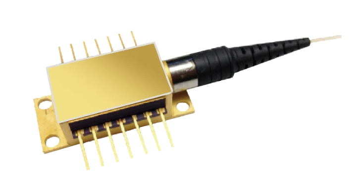
The ALM935-60-zz is the 60 mW option within a range of 1550 nm CW DFB lasers, with the zz suffix identifying the selected ITU channel. Its operating wavelength range extends from 1547 to 1561 nm, allowing configuration around the required optical channel. It is intended for use with external modulators, including LiNbO₃ Mach–Zehnder devices. The laser, optical isolator, thermoelectric cooler, thermistor and monitor photodiode are enclosed within a hermetically sealed 14-pin butterfly package. A polarisation-maintaining fibre pigtail helps maintain the optical orientation required by polarisation-sensitive modulators. Relative intensity noise is specified at no more than -160 dB/Hz over 20 to 1000 MHz, together with a maximum linewidth of 1 MHz. These characteristics support HFC and CATV architectures requiring controlled spectral and noise performance. The 60 mW option can also be considered for long-haul optical arrangements in which passive or active components introduce substantial insertion loss.
Range features
A high level overview of what this range offers
- 60 mW output option – Provides the specified optical power code for links with higher insertion-loss budgets.
- ITU-grid wavelength selection – Allows the ordering code to be matched to the required optical channel.
- 1547 to 1561 nm wavelength range – Covers multiple channels around the 1550 nm transmission window.
- Maximum 1 MHz spectral linewidth – Provides a narrow optical spectrum for externally modulated systems.
- RIN of no more than -160 dB/Hz – Helps control laser intensity noise across the specified 20 to 1000 MHz range.
- Minimum 30 dB side-mode suppression – Limits power in unwanted longitudinal modes.
- Minimum 30 dB optical isolation – Reduces the effect of reflected optical power returning to the laser.
- Integrated TEC, thermistor and monitor photodiode – Supports closed-loop temperature and optical power control.
- Polarisation-maintaining fibre – Supports alignment with polarisation-sensitive external modulators.
- Hermetically sealed 14-pin butterfly package – Integrates the laser and control components within a defined optoelectronic package.
Downloads
for ALM935 1550 nm DWDM 60 mW Butterfly CW DFB Laser
What’s in this range?
All the variants in the range and a comparison of what they offer
Electro-optical characteristics
| Parameter | Symbol | Conditions | Minimum | Typical | Maximum | Unit |
|---|---|---|---|---|---|---|
Case temperature range | T₍C₎ | — | 0 | — | 65 | °C |
Operating chip temperature | T₍OP₎ | I₍F₎ = I₍OP₎ | 15 | — | 35 | °C |
Laser threshold current | I₍TH₎ | — | — | 25 | 40 | mA |
Laser operating current | I₍OP₎ | — | — | — | 500 | mA |
Laser operating voltage | V₍OP₎ | — | — | — | 2.1 | V |
Operating output power | P₍O₎ | Dependent on model code | 20 | — | — | mW |
Operating wavelength | λ₍OP₎ | I₍F₎ = I₍OP₎, T = T₍OP₎ | 1547 | — | 1561 | nm |
Side-mode suppression ratio | SMSR | I₍F₎ = I₍OP₎ | 30 | 45 | — | dB |
Optical isolation | ISO | — | 30 | 35 | — | dB |
Spectral linewidth | Δλ | FWHM | — | — | 1 | MHz |
Relative intensity noise | RIN | 20–1000 MHz | — | — | -160 | dB/Hz |
Wavelength drift with case temperature | — | 0 < T₍C₎ < 65°C | — | — | 0.001 | nm/°C |
Wavelength temperature tunability | — | 15 < T₍OP₎ < 35°C | 0.07 | — | 0.12 | nm/°C |
Monitor photodiode responsivity | r₍MPD₎ | — | 5 | — | 200 | µA/mW |
Monitor photodiode dark current | I₍D₎ | I₍OP₎ = 0 mA | — | — | 0.2 | µA |
TEC current | I₍TEC₎ | 0 < T₍C₎ < 65°C, I₍F₎ = 500 mA | -1.2 | — | 1.2 | A |
Thermistor resistance | R₍TH₎ | — | 9.5 | 10 | 10.5 | kΩ |
TE cooler voltage | V₍TH₎ | T₍OP₎ = 15–35°C over T₍C₎ | -2.5 | — | 2.5 | V |
Polarisation extinction ratio | PER | Electric field along slow axis | 18 | 20 | — | dB |
Temperature tracking error | — | 0 < T₍C₎ < 65°C | -0.5 | — | 0.5 | dB |
The 60 power code selects the 60 mW model. Electro-optical limits are stated at series level unless a particular model code is identified.
Mechanical configuration: Hermetically sealed 14-pin butterfly package with 0.9 mm diameter PM fibre, a minimum fibre length of 1 metre and a nominal pin lead length of 5 mm from the external package wall.
Ordering scheme
| Part-number element | Code | Meaning or options |
|---|---|---|
Base series | ALM935 | 1550 nm CW DFB butterfly laser range |
Output-power code | yy | 20 = 20 mW; 30 = 30 mW; 40 = 40 mW; 50 = 50 mW; 60 = 60 mW |
Wavelength code | zz | Required ITU channel number |
Worked example: ALM935-60-34 denotes the 60 mW output option for ITU channel 34 at 1550.12 nm.
Pin assignments
| Pin | Function | Pin | Function |
|---|---|---|---|
1 | Thermistor | 8 | Case ground |
2 | Thermistor | 9 | Case ground |
3 | DC laser bias negative | 10 | No connection |
4 | Monitor photodiode anode | 11 | Laser common positive/ground |
5 | Monitor photodiode cathode | 12 | Laser modulation negative |
6 | TEC positive | 13 | Laser common positive/ground |
7 | TEC negative | 14 | No connection |
Maximum ratings
| Parameter | Symbol | Conditions | Minimum | Typical | Maximum | Unit |
|---|---|---|---|---|---|---|
Storage temperature | — | Continuous | -40 | — | 85 | °C |
Monitor photodiode reverse voltage | — | 60 seconds | — | — | 15 | V |
Monitor photodiode reverse voltage | — | Continuous | — | — | 10 | V |
Forward DC laser current | — | Continuous | — | — | 500 | mA |
Reverse DC laser voltage | — | Continuous | — | — | 1 | V |
TEC current | — | Continuous | -1.9 | — | 1.9 | A |
FAQs
for ALM935 1550 nm DWDM 60 mW Butterfly CW DFB Laser
Use the part-number format ALM935-yy-zz, where yy identifies optical output power and zz identifies the required ITU channel. For the 60 mW option, the power segment is 60, resulting in the format ALM935-60-zz. Channel 34 is identified as 1550.12 nm, so ALM935-60-34 is the corresponding worked configuration. The overall operating wavelength range extends from 1547 to 1561 nm. Every supported channel is not individually enumerated, so the required channel and wavelength should be confirmed when the order code is finalised.
Yes, the laser is intended to provide a wavelength-selected optical carrier for an external modulator, including a LiNbO₃ Mach–Zehnder device. Its PM fibre has a minimum polarisation extinction ratio of 18 dB and a typical value of 20 dB, with the electric field aligned along the slow axis. The maximum spectral linewidth is 1 MHz, while side-mode suppression is at least 30 dB and typically 45 dB. These characteristics support controlled optical coupling into a polarisation-sensitive modulator. Connectorisation, modulator power handling and the required fibre-axis alignment must still be addressed at system level.
The module requires a laser current driver, a bipolar TEC controller and circuits for reading the thermistor and monitor photodiode. Laser operating current is limited to 500 mA, while operating voltage is specified up to 2.1 V. Under the stated operating conditions, TEC current extends from -1.2 to 1.2 A and TE cooler voltage from -2.5 to 2.5 V; the continuous TEC current rating is ±1.9 A. The internal thermistor has a nominal resistance of 10 kΩ, with limits of 9.5 and 10.5 kΩ. Driver interlocks should prevent excessive forward current, reverse laser voltage above 1 V and operation outside the permitted temperature range.
Wavelength control depends on maintaining the laser chip between 15 and 35°C while the case remains within 0 to 65°C. The maximum wavelength drift with case temperature is 0.001 nm/°C across the stated case-temperature range. At that coefficient, a full 65°C case-temperature change corresponds to a calculated drift of up to 0.065 nm, provided the specified control conditions remain valid. Chip-temperature tuning is considerably larger at 0.07 to 0.12 nm/°C between 15 and 35°C. The TEC controller therefore needs adequate resolution and loop stability to hold the optical channel within the system wavelength tolerance.
Relative intensity noise is specified at no more than -160 dB/Hz across 20 to 1000 MHz, which is relevant when controlling laser-generated noise in broadband optical transmission. The maximum linewidth is 1 MHz, while side-mode suppression is at least 30 dB and typically 45 dB. Optical isolation is at least 30 dB and typically 35 dB, helping to reduce sensitivity to reflections returning from downstream components. These parameters collectively describe the quality and stability of the optical carrier. They should be assessed alongside modulator insertion loss, receiver noise, link bandwidth and reflection management rather than being used alone to predict complete link performance.
The module uses a hermetically sealed 14-pin butterfly package with a 0.9 mm PM fibre pigtail at least 1 metre long. Nominal pin lead length is 5 mm from the external package wall, which should be considered when defining the PCB footprint and package mounting arrangement. Pins 6 and 7 connect the TEC, pins 1 and 2 connect the thermistor, and pins 4 and 5 provide monitor photodiode access. Laser bias and common connections are provided through pins 3, 11 and 13, while pin 12 is the negative modulation connection. Pins 10 and 14 are not connected, and pins 8 and 9 provide case grounding.