ALM5Q 1550 nm DWDM 10 mW 1 GHz Butterfly Analogue DFB Laser
- Technology
- Analogue - RF over fibre - components
- Partner
- AGx Technologies
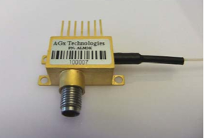
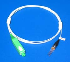
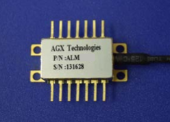
The ALM5Q 1550 nm DWDM analogue DFB laser is a directly modulated optical source for broadband analogue signal transmission. It is intended for CATV broadcast and narrowcast systems, DWDM forward-path links, QAM transport and RF-over-fibre architectures. A hermetically sealed 14-pin butterfly package integrates the laser, optical isolator, thermoelectric cooler, thermistor and monitor photodiode. Rated output selections are listed at 8, 10 and 11 dBm, while a separate series-level statement specifies optical power up to 10 mW. The minimum 1.1 GHz bandwidth and nominal 25 Ω input impedance define the main RF interface requirements. A 1 m SMF-28 pigtail with an SC/APC connector is standard for the optical connection. Because the preliminary technical data contains differences between the overview, electro-optical table and ordering information, the selected power and wavelength codes should be confirmed during component approval.
Range features
A high level overview of what this range offers
- Directly modulated DFB architecture: Allows broadband RF signals to be applied through the dedicated modulation input.
- Minimum 1.1 GHz bandwidth: Supports CATV forward-path, QAM and RF-over-fibre frequency requirements.
- High linearity and low residual chirp: Supports analogue optical links where distortion and dispersion need to be controlled.
- 8, 10 and 11 dBm output selections: Provides several optical power options for link-budget planning.
- ITU-grid wavelength options: Supports channel-specific DWDM deployment across the listed ordering range.
- Internal TEC and thermistor: Enables closed-loop control of the laser chip temperature between 15 and 35 °C.
- Integrated monitor photodiode: Provides optical output monitoring with 10 to 200 µA/mW responsivity.
- Minimum 30 dB optical isolation: Limits optical feedback into the laser cavity.
- Hermetic 14-pin butterfly package: Combines the optical, monitoring and thermal-control components in one assembly.
- SMF-28 fibre with SC/APC connector: Provides a standard single-mode optical interface with at least 40 dB return loss.
Downloads
for ALM5Q 1550 nm DWDM 10 mW 1 GHz Butterfly Analogue DFB Laser
What’s in this range?
All the variants in the range and a comparison of what they offer
Main specifications
| Category | Parameter | Symbol | Conditions or option | Minimum | Typical | Maximum | Unit |
|---|---|---|---|---|---|---|---|
Electrical | Threshold current | Ith | 25 °C | — | — | 35 | mA |
Thermal | Operating chip temperature | Top | IF = Iop | 15 | — | 35 | °C |
Electrical | Operating current | Iop | T = Top | — | — | 100 | mA |
Electrical | Operating voltage | Vop | T = Top | — | — | 2.1 | V |
Optical | Operating output power | Po | Options 08, 10 and 11; listed as minimum values | 8 / 10 / 11 | — | — | dBm |
Optical | Series-level optical-power statement | — | Feature summary | — | — | 10 | mW |
Monitoring | Monitor photodiode responsivity | rMPD | — | 10 | — | 200 | µA/mW |
Monitoring | Monitor photodiode dark current | ID | Iop = 0 mA | — | — | 0.2 | µA |
Optical | Operating wavelength | λop | IF = Iop, T = Top | 1529 | — | 1561 | nm |
Optical | Side-mode suppression ratio | SMSR | IF = Iop | 35 | — | — | dB |
Optical | Optical isolation | ISO | — | 30 | — | — | dB |
Optical | Optical return loss | ORL | — | 40 | — | — | dB |
RF | Nominal input impedance | Zin | — | — | 25 | — | Ω |
RF | Bandwidth | — | — | 1.1 | — | — | GHz |
Thermal | TEC case-temperature range | Tc | — | -20 | — | 65 | °C |
Thermal | TEC current | ITEC | -40 °C < Tc < 70 °C, IF = 100 mA | -1.0 | — | 1.6 | A |
Thermal | Thermistor resistance | RTH | — | 9.5 | — | 10.5 | kΩ |
Thermal | TE cooler voltage | VTH | Top = 15 to 35 °C over Tc | -2.5 | — | 3.8 | V |
Analogue link | Carrier-to-noise ratio | CNR | Test conditions 1 and 2 | 51 | — | — | dB |
Analogue link | Composite second order | CSO | Test condition 1 / test condition 2 | — | — | -50 / -52 | dBc |
Analogue link | Composite triple beat | CTB | Test conditions 1 and 2 | — | — | -65 | dBc |
Noise | Relative intensity noise | RIN | — | — | — | -155 | dB/Hz |
Construction | Package | — | Hermetically sealed | — | 14-pin butterfly | — | — |
Construction | Integrated components | — | — | — | Optical isolator, TEC, thermistor, laser and monitor photodiode | — | — |
Construction | Pinout | — | — | — | OC-48 compatible | — | — |
Fibre | Fibre type | — | — | — | SMF-28 | — | — |
Fibre | Fibre coating | — | — | — | Flame-retardant Hytrel | — | — |
Fibre | Pigtail diameter | — | — | — | 0.9 | — | mm |
Fibre | Pigtail length | — | — | — | 1 | — | m |
Fibre | Standard connector | — | — | — | SC/APC | — | — |
Mechanical | Nominal pin lead length | — | From the external package wall | — | 5 | — | mm |
Maximum rating at 35 °C | Storage temperature | — | Continuous | -40 | — | 85 | °C |
Maximum rating at 35 °C | Photodiode reverse voltage | — | 60 seconds | — | — | 15 | V |
Maximum rating at 35 °C | Photodiode reverse voltage | — | Continuous | — | — | 10 | V |
Maximum rating at 35 °C | Forward DC laser current | — | Continuous | — | — | 150 | mA |
Maximum rating at 35 °C | Reverse DC laser voltage | — | Continuous | — | — | 1 | V |
Maximum rating at 35 °C | TE cooler current | — | Continuous | -1.9 | — | 1.9 | A |
Test condition 1 uses rated optical power, 25 °C operation, 79-channel loading, 10 km of fibre and 0 dBm received optical power. Test condition 2 uses the same loading, temperature and received power with 5 km of fibre. The analogue results are identified as tentative.
The 10 mW series-level power statement does not align fully with the listed 11 dBm option, which is approximately 12.6 mW. Maximum ratings are protection limits rather than recommended operating points.
Pin assignments
| Pin | Function | Pin | Function |
|---|---|---|---|
1 | Thermistor | 8 | Case ground |
2 | Thermistor | 9 | Case ground |
3 | DC laser bias negative | 10 | No connection |
4 | Monitor photodiode | 11 | Laser common positive |
5 | Monitor photodiode cathode | 12 | Laser modulation negative |
6 | TEC positive | 13 | Laser common positive |
7 | TEC negative | 14 | No connection |
Ordering scheme
| Segment | Function | Available codes | Meaning |
|---|---|---|---|
ALM5Q | Product series | ALM5Q | 1550 nm analogue DFB butterfly laser series |
XX | Optical output power | 08 / 10 / 11 | 8 / 10 / 11 dBm |
ZZ | DWDM wavelength selection | 12 to 59 | ITU channel selected from the wavelength table |
Order-code format: ALM5Q-XX-ZZ
The electro-optical table identifies the output-power conditions with the ZZ prefix, while the ordering diagram assigns output power to XX and wavelength to ZZ. The ordering diagram is retained here as the order-code structure, but the selected codes should be confirmed before ordering.
ITU wavelength options
| ITU channel | Wavelength | Frequency value |
|---|---|---|
12 | 1567.95 nm | 191.2 |
13 | 1567.13 nm | 191.3 |
14 | 1566.31 nm | 191.4 |
15 | 1565.50 nm | 191.5 |
16 | 1564.68 nm | 191.6 |
17 | 1563.86 nm | 191.7 |
18 | 1563.05 nm | 191.8 |
19 | 1562.23 nm | 191.9 |
20 | 1561.42 nm | 192.0 |
21 | 1560.61 nm | 192.1 |
22 | 1559.79 nm | 192.2 |
23 | 1558.98 nm | 192.3 |
24 | 1558.17 nm | 192.4 |
25 | 1557.36 nm | 192.5 |
26 | 1556.55 nm | 192.6 |
27 | 1555.75 nm | 192.7 |
28 | 1554.94 nm | 192.8 |
29 | 1554.13 nm | 192.9 |
30 | 1553.33 nm | 193.0 |
31 | 1552.52 nm | 193.1 |
32 | 1551.72 nm | 193.2 |
33 | 1550.92 nm | 193.3 |
34 | 1550.12 nm | 193.4 |
35 | 1549.32 nm | 193.5 |
36 | 1548.51 nm | 193.6 |
37 | 1547.72 nm | 193.7 |
38 | 1546.92 nm | 193.8 |
39 | 1546.12 nm | 193.9 |
40 | 1545.32 nm | 194.0 |
41 | 1544.53 nm | 194.1 |
42 | 1543.73 nm | 194.2 |
43 | 1542.94 nm | 194.3 |
44 | 1542.14 nm | 194.4 |
45 | 1541.35 nm | 194.5 |
46 | 1540.56 nm | 194.6 |
47 | 1539.77 nm | 194.7 |
48 | 1538.98 nm | 194.8 |
49 | 1538.19 nm | 194.9 |
50 | 1537.40 nm | 195.0 |
51 | 1536.61 nm | 195.1 |
52 | 1535.82 nm | 195.2 |
53 | 1535.04 nm | 195.3 |
54 | 1534.25 nm | 195.4 |
55 | 1533.47 nm | 195.5 |
56 | 1532.68 nm | 195.6 |
57 | 1531.90 nm | 195.7 |
58 | 1531.12 nm | 195.8 |
59 | 1530.33 nm | 195.9 |
The source does not state the unit for the frequency column. Not all channel options are indicated as currently available, and the longer-wavelength entries extend beyond the 1529 to 1561 nm operating range in the electro-optical characteristics. Confirm channel availability and qualification status for the selected order code.
FAQs
for ALM5Q 1550 nm DWDM 10 mW 1 GHz Butterfly Analogue DFB Laser
The ALM5Q is intended for directly modulated broadband analogue links rather than coherent or externally modulated architectures. Its stated applications include CATV broadcast and narrowcast, DWDM forward paths, QAM transport and RF over fibre, supported by a minimum 1.1 GHz bandwidth and a nominal 25 Ω input impedance. Linearity figures include CNR of at least 51 dB, CSO limits of -50 or -52 dBc depending on fibre length, and CTB of up to -65 dBc. These figures use 79-channel loading, rated optical power, 25 °C operation and 0 dBm received power. Link performance should therefore be validated with the intended channel plan, fibre span, receiver and RF matching network.
Select the optical power first, then choose the required ITU channel from the wavelength list. The order-code diagram assigns XX to the 8, 10 or 11 dBm power option and ZZ to channels 12 through 59; 10 dBm corresponds to 10 mW, while 11 dBm is approximately 12.6 mW. The separate statement of up to 10 mW therefore conflicts with the 11 dBm option and should be resolved before production release. Wavelength selection must also account for the characterised operating range of 1529 to 1561 nm. The agreed power code, channel code and acceptance limits should be recorded in the component specification.
The laser requires closed-loop thermal control when stable wavelength and analogue performance are important. Its chip operating range is 15 to 35 °C, with an internal thermistor specified at 9.5 to 10.5 kΩ and a TEC operating envelope of -1.0 to 1.6 A under the stated condition. Cooler voltage is listed from -2.5 to 3.8 V, while the continuous absolute current limit is ±1.9 A. The controller should use current and voltage limiting, suitable loop compensation and protection against thermistor faults or open connections. Thermal margin must be checked at enclosure extremes because the characterised TEC case-temperature range is -20 to 65 °C, which differs from the storage range.
The RF interface should be designed around a nominal 25 Ω input rather than assuming a direct 50 Ω source match. The laser provides separate DC bias and modulation pins, with laser-common connections on pins 11 and 13, modulation on pin 12 and DC bias on pin 3. Operating current is specified up to 100 mA and operating voltage up to 2.1 V, while the minimum bandwidth is 1.1 GHz. A matching or transformation network may therefore be needed to control reflections, modulation depth and frequency response from the selected RF driver. The final layout should keep the modulation path short, provide the specified case grounds and verify linearity across the actual channel loading.
The analogue figures provide an initial link-budget reference, but they should not be treated as universal system results. CNR is listed at a minimum of 51 dB, CSO at a maximum of -50 dBc for the 10 km condition and -52 dBc for the 5 km condition, CTB at a maximum of -65 dBc, and RIN at a maximum of -155 dB/Hz. The distortion tests use 79-channel loading, rated optical power, 25 °C and 0 dBm received optical power. Receiver noise, fibre dispersion, connector losses and RF drive linearity can move the system result away from these values. Prototype testing should reproduce the intended fibre span and channel plan before design freeze.
The package combines the laser, optical isolator, TEC, thermistor and monitor photodiode in a hermetically sealed 14-pin butterfly body. Its standard pigtail is 1 m of SMF-28 fibre with a 0.9 mm flame-retardant Hytrel coating and an SC/APC connector, while nominal pin lead length is 5 mm from the package wall. Minimum optical isolation is 30 dB and minimum optical return loss is 40 dB. Mechanically, the design must protect the pigtail bend radius and avoid transferring connector strain into the package. Electrically, pins 8 and 9 provide case ground, while unused pins 10 and 14 should remain unconnected.
The maximum ratings are protection boundaries rather than normal operating targets. At the stated 35 °C rating condition, storage temperature is -40 to 85 °C, continuous forward laser current is limited to 150 mA, reverse laser voltage to 1 V and continuous TEC current to ±1.9 A. The monitor photodiode reverse-voltage limit is 10 V continuously or 15 V for 60 seconds. Driver start-up, shutdown and fault behaviour should prevent overshoot beyond these limits, particularly during TEC saturation or bias sequencing. ESD controls, current limiting and temperature interlocks should be defined at equipment level because no separate ESD rating is provided.
Not every wavelength in the ordering list falls inside the electro-optical operating range stated for the series. The ordering table covers channels 12 through 59, with wavelength entries from 1567.95 to 1530.33 nm, whereas the electro-optical table specifies 1529 to 1561 nm. Not all listed wavelengths are stated to be available, so channel availability and qualification status need confirmation for each order code. This is particularly relevant to the longer-wavelength entries above 1561 nm, where the two ranges do not align. For production control, require a confirmed wavelength, output-power code and acceptance limits on the purchase specification rather than relying only on the generic series code.