CT-0155TSP-MB5L-E 2M 1310 nm FP 20 km 2 Mb/s SFP Transceiver w. DDMI
- Technology
- Optical transceivers
- Partner
- Coretek
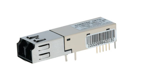
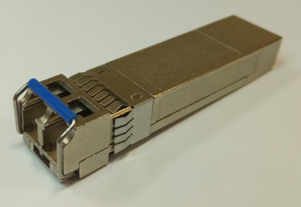
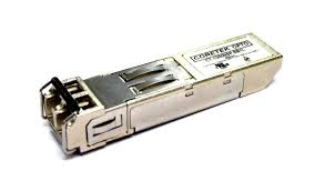
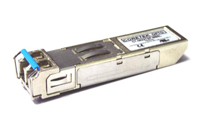
The CT-0155TSP-MB5L-E 2M SFP transceiver provides optical-to-electrical conversion for 2 Mb/s serial communication links. It uses a 1310 nm Fabry–Pérot laser and is specified for distances of up to 20 km over single-mode fibre. A duplex LC receptacle provides separate transmit and receive paths within the compact SFP form factor. The module is designed for equipment implementing IEEE C37.94 or IEC 62843 communication interfaces. It operates from a nominal 3.3 V supply and uses an AC/AC differential electrical interface with NRZ encoding. SFF-8472 digital diagnostic monitoring provides access to temperature, supply voltage, laser bias current, transmitted optical power and received optical power. Its −40 to +85 °C case operating range supports installations exposed to wide temperature variations.
Range features
A high level overview of what this range offers
- 2 Mb/s NRZ operation – Matches fixed-rate IEEE C37.94 and IEC 62843 optical communication interfaces.
- 1310 nm FP laser – Provides transmission over single-mode fibre at the specified wavelength.
- 20 km rated reach – Supports intermediate-distance optical links when the complete loss budget remains within specification.
- Duplex LC receptacle – Provides separate transmit and receive connections in a compact interface.
- SFP MSA form factor – Supports integration into compatible SFP host cages.
- 3.3 V operation – Uses the standard supply arrangement found in SFP host equipment.
- SFF-8472 digital diagnostics – Allows operating temperature, voltage, bias current and optical power to be monitored through the serial interface.
- −40 to +85 °C case temperature range – Supports operation across extended environmental conditions.
- Tx Disable, Tx Fault and LOS signals – Gives the host access to transmitter control and link-status information.
- Class 1 laser classification – Supports controlled use within the stated laser-safety requirements.
- RoHS-compliant, lead-free construction – Supports equipment subject to restricted-substance requirements.
Downloads
for CT-0155TSP-MB5L-E 2M 1310 nm FP 20 km 2 Mb/s SFP Transceiver w. DDMI
What’s in this range?
All the variants in the range and a comparison of what they offer
Specifications
| Specification | Value |
|---|---|
Product code | CT-0155TSP-MB5L-E 2M |
Product type | Optical SFP transceiver with digital diagnostic monitoring |
Supported interfaces | IEEE C37.94 and IEC 62843 |
Data rate | 2 Mb/s |
Encoding | NRZ |
Fibre type | 9/125 µm single-mode fibre |
Optical connector | Duplex LC receptacle |
Rated transmission distance | 20 km |
Transmitter type | 1310 nm FP laser diode |
Centre wavelength | 1270 to 1350 nm; 1310 nm typical |
Transmitted optical power | −19 to −11 dBm |
Extinction ratio | 12 dB minimum |
RMS spectral width | 3 nm maximum |
Optical rise time | 10 ns maximum, measured from 10% to 90% |
Optical fall time | 10 ns maximum, measured from 90% to 10% |
Optical output eye | ITU-T G.957 compliant |
Receiver sensitivity | −34 dBm or lower, measured with a 2⁷−1 PRBS at a BER below 10⁻¹⁰ |
Maximum receiver input power | −3 dBm |
Receiver operating wavelength | 1100 to 1600 nm |
LOS asserted limit | −45 dBm |
LOS deasserted limit | −33 dBm |
LOS hysteresis | 0.5 dB minimum |
Electrical interface | AC/AC differential |
Data input voltage swing | 400 to 1600 mV |
Receiver differential output voltage | 0.4 to 1.3 V |
Nominal supply voltage | 3.3 V |
Operating supply range | 3.1 to 3.5 V |
Absolute maximum supply voltage | 0 to 6 V |
Transmitter supply current | 200 mA maximum |
Receiver supply current | 100 mA maximum |
Case operating temperature | −40 to +85 °C |
Storage temperature | −40 to +85 °C |
Tx Disable low level | 0 to 0.8 V |
Tx Disable high level | 2.0 V to Vcc |
Tx Fault and LOS low level | 0 to 0.8 V |
Tx Fault and LOS high level | 2.0 V to Vcc |
MOD-DEF low level | −0.6 V to 0.3 × Vcc |
MOD-DEF high level | 0.7 × Vcc to Vcc + 0.5 V |
Tx Disable assertion time | 10 µs maximum |
Tx Disable negation time | 1 ms maximum |
Initialisation time, including Tx Fault reset | 300 ms maximum |
Tx Fault assertion time | 100 µs maximum |
Tx Disable reset-start time | 10 µs maximum |
LOS assertion and deassertion time | 100 µs maximum |
Digital diagnostic interface | SFF-8472-compatible I²C serial interface |
Monitored parameters | Temperature, supply voltage, laser bias current, transmitted power and received power |
Reliability qualification reference | Telcordia GR-468-CORE |
Environmental compliance | RoHS compliant and lead-free |
Laser classification | Class 1 laser product, hazard level 1 |
Laser-safety standards | IEC 60825-1 Ed. 2:2007-03 and applicable FDA laser-product requirements |
Digital Diagnostic Monitoring Specification
| Monitored parameter | Measurement range | Accuracy | Calibration |
|---|---|---|---|
Temperature | −40 to +85 °C | ±3 °C | Internal |
Supply voltage | 3.0 to 3.6 V | ±3% | Internal |
Laser bias current | 0 to 70 mA | ±10% | Internal |
Transmitted optical power | −19 to −11 dBm | ±3 dB | Internal |
Received optical power | −30 to −3 dBm | ±3 dB | Internal |
Digital Diagnostic Alarm and Warning Thresholds
| Parameter | Alarm low | Alarm high | Warning low | Warning high |
|---|---|---|---|---|
Temperature | −40 °C | +110 °C | −35 °C | +100 °C |
Supply voltage | 3.0 V | 3.6 V | 3.1 V | 3.5 V |
Laser bias current | 2 mA | 80 mA | 4 mA | 70 mA |
Transmitted optical power | −20 dBm | −10 dBm | −19 dBm | −11 dBm |
Received optical power | −35 dBm | −2 dBm | −34 dBm | −3 dBm |
Pin Assignment
| Pin | Signal | Function |
|---|---|---|
1 | VeeT | Transmitter ground |
2 | Tx Fault | Transmitter fault indication |
3 | Tx Disable | Disables the transmitter when high or left open |
4 | MOD-DEF(2) | Two-wire serial identification interface |
5 | MOD-DEF(1) | Two-wire serial identification interface |
6 | MOD-DEF(0) | Grounded within the module |
7 | Rate Select | Not connected |
8 | LOS | Loss-of-signal indication |
9 | VeeR | Receiver ground |
10 | VeeR | Receiver ground |
11 | VeeR | Receiver ground |
12 | RD− | Inverted received-data output |
13 | RD+ | Non-inverted received-data output |
14 | VeeR | Receiver ground |
15 | VccR | Receiver supply |
16 | VccT | Transmitter supply |
17 | VeeT | Transmitter ground |
18 | TD+ | Non-inverted transmitter-data input |
19 | TD− | Inverted transmitter-data input |
20 | VeeT | Transmitter ground |
FAQs
for CT-0155TSP-MB5L-E 2M 1310 nm FP 20 km 2 Mb/s SFP Transceiver w. DDMI
Yes, the transceiver is specifically designed for equipment implementing IEEE C37.94 or IEC 62843 optical interfaces. It operates at 2 Mb/s using NRZ encoding and converts an AC/AC differential electrical interface into a single-mode optical link. The module uses a standard SFP form factor and a duplex LC receptacle, but its data rate and interface behaviour differ from conventional Ethernet SFPs. The host must therefore provide the required 2 Mb/s signalling, control pins and 3.3 V supply arrangement. Mechanical SFP compatibility alone should not be treated as confirmation of electrical or protocol compatibility.
A conservative nominal power budget of 15 dB is obtained by comparing the minimum transmitted power of −19 dBm with the −34 dBm receiver sensitivity. Fibre attenuation at 1310 nm, connector losses, splice losses, patch leads, ageing, temperature effects and a suitable engineering margin must all be deducted from this figure. The maximum transmitted power is −11 dBm, while the receiver tolerates up to −3 dBm, leaving 8 dB of input headroom even before path attenuation is considered. The 20 km rating is therefore a reach classification rather than a substitute for a route-specific calculation. End-to-end optical loss should be measured before commissioning the link.
The digital diagnostic interface monitors module temperature, supply voltage, laser bias current, transmitted power and received power through an SFF-8472-compatible I²C interface. Temperature is measured from −40 to +85 °C with ±3 °C accuracy, while voltage is measured from 3.0 to 3.6 V with ±3% accuracy. Bias-current accuracy is ±10%, and both optical power readings have a stated accuracy of ±3 dB. The calibrated received-power range is −30 to −3 dBm, even though receiver sensitivity extends to −34 dBm. Readings close to the sensitivity limit may therefore fall outside the stated DDMI accuracy range and should be confirmed with suitable optical test equipment when precise measurements are required.
The host must provide a regulated supply between 3.1 and 3.5 V. The stated transmitter and receiver current limits are 200 mA and 100 mA respectively, so a simple combined design estimate is 300 mA. This corresponds to approximately 0.99 W at 3.3 V or 1.05 W at the maximum operating voltage if both current limits occur simultaneously. Airflow, cage temperature, adjacent modules and enclosure conditions must keep the module case between −40 and +85 °C. DDMI temperature and voltage readings can support operational supervision, but the host power and thermal design should still be validated under worst-case supply and ambient conditions.
The host should allow up to 300 ms for module initialisation, including reset of the Tx Fault condition. Tx Disable can take up to 10 µs to assert and 1 ms to negate, while Tx Fault may require up to 100 µs to indicate a transmitter fault. Receiver LOS assertion and deassertion can each take up to 100 µs. The differential transmitter input accepts a 400 to 1600 mV swing, and the receiver provides a differential output between 0.4 and 1.3 V. Start-up sequencing and protection switching should include these delays rather than assuming that control and status signals respond instantaneously.
The module is intended for 9/125 µm single-mode fibre and uses a duplex LC receptacle. One fibre carries the transmitted signal and the other carries the received signal, so the link must be installed with the correct transmit-to-receive polarity. The FP transmitter has a typical centre wavelength of 1310 nm, with a specified range from 1270 to 1350 nm. Although the receiver responds across 1100 to 1600 nm, the intended link configuration remains a 1310 nm single-mode connection. Connector end faces should be inspected and cleaned before connection because contamination can consume part of the available 15 dB conservative optical budget.
The transceiver is classified as a Class 1 laser product and is specified against IEC 60825-1 Ed. 2:2007-03 and applicable FDA laser-product requirements. It also uses RoHS-compliant, lead-free construction and follows the SFP MSA and SFF-8472 diagnostic interface arrangements. The optical module is designed with FCC Class B limits and radio-frequency immunity in mind, but final EMC performance depends on the host enclosure, grounding, power filtering, PCB layout and external cabling. Complete equipment may also require testing against EN 55022 or CISPR 22 requirements. Compliance of the module does not remove the need to assess the finished system in its intended configuration.
LOS and Tx Fault should be treated as status indicators rather than direct measurements of link error rate. The receiver has an LOS asserted limit of −45 dBm, a deasserted limit of −33 dBm and at least 0.5 dB of hysteresis, with a response time of up to 100 µs. Because receiver sensitivity is specified at −34 dBm for a BER below 10⁻¹⁰, the LOS state should not be assumed to identify the exact point at which data errors begin. Tx Fault and Tx Disable allow the host to identify and isolate transmitter faults, but their specified timing must be included in the control sequence. Reliable switching decisions should combine status pins, DDMI readings and communication-protocol checks.