SMD RTD elements
- Technology
- Platinum RTD sensors
- Partner
- YAGEO Nexensos GmbH
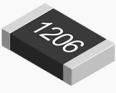
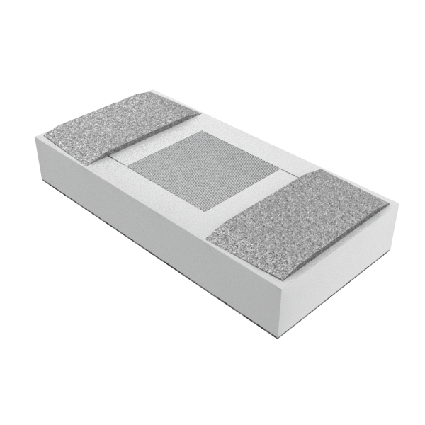
The SMD 1206 SC Pt1000 RTD elements provide board-level temperature measurement where the sensor must be positioned close to a semiconductor die or another concentrated heat source. Full-area AgPd backside metallisation is designed for silver sintering and creates a short thermal path between the heat source and sensing element. AgPt pads on the upper surface support ultrasonic bonding with thick aluminium wire. This arrangement keeps the electrical connections on top and permits potential-free positioning, subject to the insulation design and validation of the finished assembly.
The Pt1000 characteristic has a temperature coefficient of 3850 ppm/K and tolerance class F 0.6 (2B) across the continuous operating range from -50 to +200 °C. Part numbers 5164075 and 5195006 share the same sensing, mechanical and electrical design but are supplied on a wafer frame and in a blister reel respectively. The elements are suitable for power-electronics boards, compact power modules and assemblies requiring a short thermal path between the temperature sensor and a semiconductor or substrate.
Range features
A high level overview of what this range offers
- Pt1000 platinum sensing element with 3850 ppm/K TCR: Supports temperature measurement based on the DIN EN IEC 60751 characteristic.
- F 0.6 (2B) tolerance from -50 to +200 °C: Provides a defined component tolerance throughout the stated continuous operating range.
- Full-area backside sintering interface: Creates a short thermal path between the sensing element and heat source.
- AgPd backside metallisation: Supports mounting by silver sintering.
- AgPt upper metallisation: Supports ultrasonic bonding with thick aluminium wire.
- Potential-free positioning arrangement: Allows installation directly on or close to heat-generating components, subject to system-level insulation requirements.
- Maximum R₀ drift of 0.23% after defined stress tests: Provides a specified component-ageing allowance for long-term error calculations.
- Self-heating below 0.4 K/mW when unassembled: Helps engineers estimate measurement error caused by excitation current.
- Wafer-frame and blister-reel variants: Supports different component-handling and production processes.
- MSL 1 classification: Provides unrestricted floor life under the stated moisture-sensitivity classification.
Downloads
for SMD RTD elements
What’s in this range?
All the variants in the range and a comparison of what they offer
Specifications
| Specification | Value |
|---|---|
Product series | SMD 1206 SC Sinter |
Sensor technology | Platinum resistance temperature detector |
Standard | DIN EN IEC 60751 |
Nominal resistance R₀ | Pt1000 |
Tolerance class | F 0.6 (2B) |
Continuous tolerance-class range | -50 to +200 °C |
Temperature coefficient | 3850 ppm/K |
Measuring current | 0.1 to 0.3 mA |
Self-heating | <0.4 K/mW, unassembled |
Insulation resistance |
|
Theoretical dielectric strength | 7.5 kV; assembly processing and encapsulation can reduce the achieved value |
Length L1 | 3.1 ±0.15 mm |
Width | 1.5 ±0.15 mm |
Height | 0.55 ±0.15 mm |
Terminal length L2 | 0.79 mm, reference value |
Upper metallisation | AgPt thick-film surface for thick-wire ultrasonic bonding |
Backside metallisation | AgPd thick-film surface for silver sintering |
Recommended bonding wire | Al H11 thick wire, 300 µm diameter |
Backside shear strength after sintering |
|
Upper-side bond pull force |
|
Maximum long-term R₀ drift | ≤0.23% after each independently conducted standard test |
Long-term test conditions | 1,000 hours at +200 °C and ≥0.1 mA; 1,000 hours at +85 °C and 85% relative humidity; 1,000 cycles from -40 to +150 °C |
Blister-reel orientation and capacity | Face-up; maximum 4,200 pieces per reel |
Storage life | Minimum nine months in unopened original packaging |
Moisture sensitivity level | MSL 1, unrestricted |
Additional options | Other resistance values and tolerance classes available on request |
Variant comparison
| Specification | Variant 1 | Variant 2 |
|---|---|---|
Part number | 5164075 | 5195006 |
Packaging | Wafer frame | Blister reel |
Nominal resistance | Pt1000 | Pt1000 |
Tolerance class | F 0.6 (2B) | F 0.6 (2B) |
Temperature range | -50 to +200 °C | -50 to +200 °C |
Mechanical and electrical design | Common SMD 1206 SC specification | Common SMD 1206 SC specification |
FAQs
for SMD RTD elements
Part number 5164075 is supplied on a wafer frame, while 5195006 is supplied in a blister reel. The sensing element is common to both variants: Pt1000 with a 3850 ppm/K temperature coefficient, F 0.6 (2B) tolerance, a -50 to +200 °C continuous range and the same SMD 1206 SC dimensions. The face-up reel holds up to 4,200 pieces and is suitable for reel-based component handling. The wafer-frame version is intended for production equipment configured for die or frame handling before sintering. Both formats have an MSL 1 classification and a minimum unopened storage period of nine months, so selection is primarily an assembly-logistics decision.
Yes, provided the assembly process supports backside silver sintering and upper-side ultrasonic thick-wire bonding. The backside has AgPd thick-film metallisation, with sintered-joint shear strength specified above 10 N/mm² minimum and above 20 N/mm² mean. The upper AgPt surface is intended for bonding and has a stated pull force above 210 cN when evaluated with 300 µm Al H11 thick wire. Positioning the sensor close to the die shortens the thermal path and can reduce the temperature difference between the sensing element and heat source. The finished design still requires process validation covering the substrate finish, sinter paste, pressure, thermal cycle, bond settings and encapsulation.
Use a measuring current between 0.1 and 0.3 mA, choosing the lowest value that still provides the required signal quality and noise margin. At approximately 1,000 Ω, this current range produces about 0.01 to 0.09 mW of electrical power in the sensor. Applying the unassembled self-heating coefficient of less than 0.4 K/mW gives an estimated temperature rise below approximately 0.004 to 0.036 K under that reference condition. Actual self-heating depends on the sinter joint, substrate, airflow, encapsulation and surrounding thermal mass. The assembled sensor should therefore be verified at the intended excitation current, sampling duty cycle and operating temperature.
F 0.6 (2B) defines the element’s permitted deviation from the nominal DIN EN IEC 60751 resistance-temperature characteristic during continuous operation from -50 to +200 °C. The 3850 ppm/K temperature coefficient establishes the nominal resistance slope used by the measurement circuit. This component tolerance does not include excitation-current accuracy, analogue front-end error, ADC error, interconnection resistance, thermal gradients or self-heating. A system-level error budget should combine all these contributions across the operating range rather than treating the RTD class as the accuracy of the finished instrument. Calibration can correct repeatable electronic offsets, but mounting-related thermal errors must be evaluated in the actual assembly.
Applications above +200 °C are indicated as possible, but the declared F 0.6 (2B) continuous tolerance range ends at +200 °C. The long-term test programme includes 1,000 hours at +200 °C and 1,000 temperature cycles between -40 and +150 °C, rather than a defined tolerance or service-life rating above +200 °C. Engineers should not extrapolate the specified class accuracy, drift or insulation behaviour beyond the declared range. Sinter-joint materials, bond wires, substrate expansion and encapsulation may also become limiting factors at higher temperatures. Operation above +200 °C should therefore be treated as a separately validated application with explicitly agreed performance limits.
Maximum R₀ drift is limited to 0.23% after each of three independently performed tests: 1,000 hours at +200 °C, 1,000 hours at +85 °C and 85% relative humidity, and 1,000 cycles from -40 to +150 °C. For a Pt1000 element, 0.23% corresponds to 2.3 Ω at 0 °C. With a nominal sensitivity of approximately 3.85 Ω/K near 0 °C, that resistance change is equivalent to roughly 0.6 K before other errors are included. The tests are independent and do not represent every possible combination of humidity, excitation current, temperature cycling and mounting stress. Use the 0.23% limit as a component-level ageing contribution and add suitable system margin for the intended operating profile.
No, the 7.5 kV value is a theoretical component-level figure based on the substrate material properties and sensor geometry. Assembly processing, encapsulation, the selected potting material and the shape of the potting meniscus can reduce the achieved withstand voltage. The separate insulation resistance above 1,000 MΩ at 20 °C indicates low leakage under the stated condition, but it does not replace high-voltage qualification. Creepage, clearance, substrate construction, contamination, humidity and thermal cycling must be assessed at module level. The finished assembly should be validated using the withstand-voltage and insulation tests required for its working voltage and applicable safety standard.