M Series RTD sensors
- Technology
- Platinum RTD sensors
- Partner
- YAGEO Nexensos GmbH
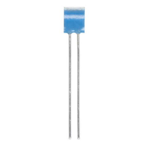
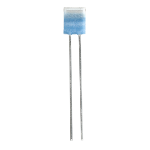
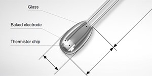
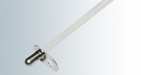
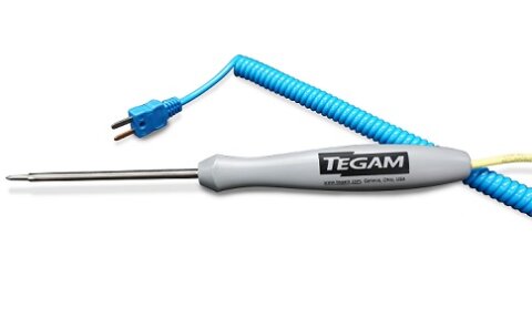
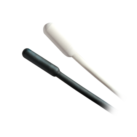
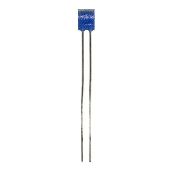
The M Series is a range of wired Pt-RTD elements designed for integration into probes, sleeves and compact temperature-sensing assemblies. It includes M1020, M213, M222, M308, M310 and M416 formats for selecting the required footprint, nominal resistance and tolerance class. The platinum resistance characteristic has a temperature coefficient of 3850 ppm/K, supporting standardised signal conditioning and sensor interchangeability. Depending on the model, Pt100, Pt500 and Pt1000 nominal resistance values are available with tolerance classes from F 0.1 to F 0.3.
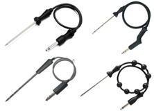
Continuous operating ranges extend from -70 °C to +500 °C for suitable variants, with temporary operation up to +550 °C for class F 0.3 elements. Compact geometries accommodate restricted probe diameters, including the narrow M308 for installation diameters below 1 mm. Platinum-clad nickel leads support welding, crimping and brazing during probe assembly. Applications include pyrolytic ovens, domestic appliances, HVAC equipment, medical devices, laboratory instruments, server cooling, battery monitoring and industrial process control.
Range features
A high level overview of what this range offers
- DIN EN IEC 60751 characteristic – Supports standardised RTD measurement and calibration methods.
- 3850 ppm/K temperature coefficient – Simplifies integration with common platinum RTD interfaces.
- Pt100, Pt500 and Pt1000 options – Provide flexibility for different cable lengths, excitation circuits and input stages.
- F 0.1, F 0.15 and F 0.3 tolerance classes – Allow accuracy to be matched to the required operating range.
- Continuous operation from -70 °C to +500 °C – Supports low-temperature monitoring and high-temperature process measurement with suitable variants.
- Temporary operation up to +550 °C – Provides short-duration temperature capability for class F 0.3 variants.
- Platinum-clad nickel leads – Support welding, crimping and brazing into probe assemblies.
- Multiple element geometries – Accommodate probe fit diameters from below 1 mm to approximately 2.6 mm among the specified models.
- Specified vibration and shock resistance – Supports mechanically demanding installations when the element is mounted correctly.
- RoHS-compliant variants – Assist with restricted-substance requirements in equipment design.
What’s in this range?
All the variants in the range and a comparison of what they offer
Specifications
| Parameter | Specification |
|---|---|
Product type | Wired thin-film platinum resistance temperature detector elements |
Measurement principle | Platinum resistance temperature detection |
Applicable standard | DIN EN IEC 60751 |
Temperature coefficient | 3850 ppm/K |
Nominal resistance options | Pt100, Pt500 and Pt1000, model-dependent |
Tolerance classes | F 0.1 (1/3 B), F 0.15 (A) and F 0.3 (B), model-dependent |
Class F 0.1 temperature range | 0 °C to +150 °C |
Class F 0.15 temperature range | -50 °C to +300 °C |
Class F 0.3 temperature range | -70 °C to +500 °C |
Temporary temperature capability | Up to +550 °C for class F 0.3 variants |
Measuring current, Pt100 | 0.3 to 1 mA |
Measuring current, Pt500 | 0.1 to 0.7 mA |
Measuring current, Pt1000 | 0.1 to 0.3 mA |
Lead type | Platinum-clad nickel wire |
Connection methods | Welding, crimping and brazing |
Lead length | 7 mm or 10 mm on the listed core variants |
Self-heating coefficient | 0.2 to 0.6 K/mW at 0 °C, model-dependent |
Insulation resistance at 20 °C | Greater than 100 MΩ for specified core variants |
Insulation resistance at 500 °C | Greater than 2 MΩ for specified core variants |
Vibration resistance | At least 40 g from 10 to 2,000 Hz, dependent on installation |
Shock resistance | At least 100 g with an 8 ms half-sine pulse, dependent on installation |
Typical long-term R₀ drift | 0.04% after 1,000 hours at +500 °C for established core variants |
Storage life | At least 12 months in the original packaging |
Packaging | Plastic bag or blister reel, model-dependent |
Environmental compliance | RoHS-compliant variants |
Core Variant Comparison
| Model | Length L | Width W | Height H | Lead length LL | Self-heating at 0°C |
|---|---|---|---|---|---|
M213 | 1.7 ± 0.25 | 1.25 ± 0.15 | 0.8 ± 0.2 | 10 ± 1 | 0.6 K/mW |
M220 | 2.3 +0.2/−0.1 | 1.9 ± 0.2 | 0.9 +0.3/−0.2 | 10 ± 1 | 0.4 K/mW |
M416 | 3.9 +0.2/−0.1 | 1.5 ± 0.2 | 0.9 +0.3/−0.2 | 10 ± 1 | 0.4 K/mW |
M422 | 4.0 +0.2/−0.1 | 2.1 ± 0.2 | 0.9 +0.3/−0.2 | 10 ± 1 | 0.3 K/mW |
M1020 | 9.5 ± 0.15 | 1.9 ± 0.2 | 0.9 +0.3/−0.2 | 10 ± 1 | 0.2 K/mW |
Available configurations
| Model | R₀ | Tolerance class | Operating range | Packaging |
|---|---|---|---|---|
M213 | Pt100 | F 0.3 (B) | −70 to +500°C | Plastic bag |
M213 | Pt100 | F 0.15 (A) | −50 to +300°C | Plastic bag |
M213 | Pt100 | F 0.1 (1/3 B) | 0 to +150°C | Plastic bag |
M213 | Pt1000 | F 0.3 (B) | −70 to +500°C | Plastic bag |
M220 | Pt100 | F 0.3 (B) | −70 to +500°C | Blister reel |
M220 | Pt100 | F 0.15 (A) | −50 to +300°C | Blister reel |
M220 | Pt100 | F 0.1 (1/3 B) | 0 to +150°C | Plastic bag |
M220 | Pt100 | F 0.1 (1/3 B) | 0 to +150°C | Blister reel |
M416 | Pt100 | F 0.3 (B) | −70 to +500°C | Plastic bag |
M416 | Pt100 | F 0.3 (B) | −70 to +500°C | Blister reel |
M416 | Pt100 | F 0.15 (A) | −50 to +300°C | Plastic bag |
M416 | Pt100 | F 0.15 (A) | −50 to +300°C | Blister reel |
M416 | Pt100 | F 0.1 (1/3 B) | 0 to +150°C | Plastic bag |
M422 | Pt100 | F 0.3 (B) | −70 to +500°C | Plastic bag |
M422 | Pt500 | F 0.3 (B) | −70 to +500°C | Plastic bag |
M1020 | Pt100 | F 0.3 (B) | −70 to +500°C | Plastic bag |
M1020 | Pt100 | F 0.3 (B) | −70 to +500°C | Blister reel |
M1020 | Pt100 | F 0.15 (A) | −50 to +300°C | Blister reel |
M1020 | Pt100 | F 0.1 (1/3 B) | 0 to +150°C | Plastic bag |
M1020 | Pt100 | F 0.1 (1/3 B) | 0 to +150°C | Blister reel |
M1020 | Pt1000 | F 0.3 (B) | −70 to +500°C | Plastic bag |
M1020 | Pt1000 | F 0.3 (B) | −70 to +500°C | Blister reel |
M1020 | Pt1000 | F 0.15 (A) | −50 to +300°C | Plastic bag |
M1020 | Pt1000 | F 0.15 (A) | −50 to +300°C | Blister reel |
M1020 | Pt1000 | F 0.1 (1/3 B) | 0 to +150°C | Plastic bag |
FAQs
for M Series RTD sensors
The M308 should be considered when the sensor must fit within a probe or tube having an internal diameter below 1 mm. It is intended for restricted installation spaces and uses 7 mm leads, compared with the 10 mm leads used by the other core variants. For comparison, the M310 supports a minimum fit diameter of approximately 1.6 mm, the M213 approximately 1.8 mm and the M222 approximately 2.6 mm. The M308 is therefore relevant to wearables, compact medical equipment, battery monitoring and small thermal assemblies. Mechanical clearance, insulation and the effect of encapsulation on response time must still be checked in the completed probe design.
The tolerance class should be selected by considering both the required accuracy and the complete continuous operating range. Class F 0.1 applies from 0 °C to +150 °C, class F 0.15 from -50 °C to +300 °C and class F 0.3 from -70 °C to +500 °C. A tighter class cannot automatically be extended across the wider temperature range assigned to class F 0.3. Class F 0.3 variants may also be used temporarily at temperatures up to +550 °C, but this is not their continuous class range. Engineers should therefore specify the class against every critical measurement point rather than selecting it only from the nominal system temperature.
Pt100 is suitable for established industrial instrumentation and interfaces designed around a 100 Ω sensor at 0 °C. Pt1000 produces a larger resistance change per degree and can reduce the proportional influence of lead resistance, which is useful in compact electronics and lower-current measurement circuits. Pt500 provides an intermediate option and is available within the M222 family. The permissible measuring-current ranges are 0.3 to 1 mA for Pt100, 0.1 to 0.7 mA for Pt500 and 0.1 to 0.3 mA for Pt1000. The final choice should account for the analogue front-end range, wiring configuration, cable resistance, electrical noise and allowable self-heating error.
Self-heating is controlled by limiting electrical power in the RTD and ensuring adequate thermal coupling to the measured medium. The specified measuring currents should be treated as operating boundaries rather than automatic design targets, particularly in still air or poorly conducting encapsulants. At 0 °C, a Pt1000 driven at 0.3 mA dissipates approximately 0.09 mW, corresponding to an estimated temperature rise of about 0.018 to 0.054 K across self-heating coefficients of 0.2 to 0.6 K/mW. Lower current or pulsed excitation can reduce this contribution when the input circuit has sufficient resolution. Validation should be performed after the element is installed because the finished assembly changes the heat-transfer conditions.
The core M Series elements use platinum-clad nickel leads intended for welding, crimping and brazing. The joining method should be selected around the probe material, thermal cycle, electrical resistance and production-volume requirements. Welding can provide a compact metallic joint, while crimping avoids introducing a brazing thermal cycle into the element area. Brazing may suit probe constructions that require a metallurgical joint but demands controlled heat input and suitable process materials. In every case, the sensor body and lead exit should be protected from mechanical loading, and the completed joint should be checked for contact resistance, pull strength and insulation performance.
Response time depends strongly on the selected model, test medium, flow rate and final mounting arrangement. The M308 reaches t0.5 in 0.03 seconds and t0.9 in 0.09 seconds in water flowing at 0.3 m/s, while its corresponding air values at 3 m/s are 1.4 and 3.5 seconds. In water flowing at 0.4 m/s, the M310 is rated at 0.04 and 0.12 seconds, the M222 at 0.05 and 0.15 seconds, and the M416 at 0.06 and 0.18 seconds. Air response is slower because convective heat transfer is lower. Probe walls, potting compounds, sleeves and thermal contact resistance will normally increase the response time of the finished assembly.
The elements are specified for vibration of at least 40 g from 10 to 2,000 Hz and shock of at least 100 g with an 8 ms half-sine pulse, but both ratings depend on installation. These values do not remove the need for strain relief, lead support and controlled encapsulation around the sensor body. Established core variants show a typical R₀ drift of 0.04% after 1,000 hours at +500 °C, which is approximately equivalent to 0.10 °C near 0 °C for a 3850 ppm/K platinum characteristic. Repeated thermal cycling and assembly stress can add further error. Qualification testing should therefore use the actual probe construction, mounting orientation and anticipated vibration spectrum.
Standard catalogue elements should not automatically be treated as carrying a complete automotive qualification or submission package. The platinum characteristic, vibration capability and operating-temperature range may suit automotive sensing tasks, but project requirements can also include IMDS records, PPAP documentation, traceability controls and application-specific validation. These requirements must be confirmed for the selected order number before it is released into the design. The intended joining process, encapsulation material, thermal-cycling profile and failure-mode controls should also be reviewed at assembly level. Early confirmation avoids selecting an electrically suitable RTD that cannot meet the programme documentation or production approval process.