H540 S high-temperature micro heater sensor
- Technology
- Platinum RTD sensors
- Partner
- YAGEO Nexensos GmbH
A compact, high-temperature heating element engineered for rapid, precise and stable thermal performance.
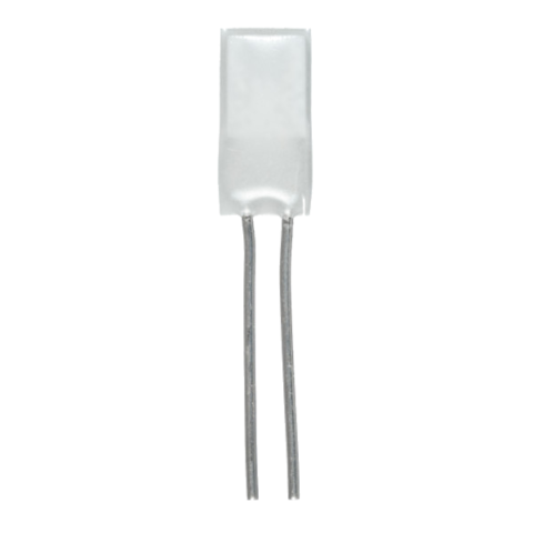
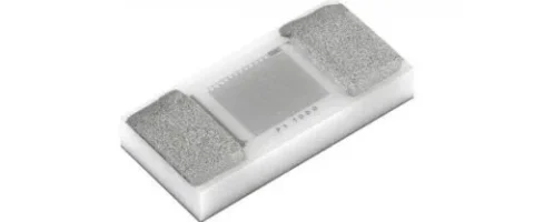
The YAGEO Nexensos H540 S is a miniature platinum thin-film heater designed for applications requiring a small, controllable heat source at elevated temperatures. Measuring just 5.2 × 3.9 × 1.0 mm, it combines a platinum heating element with a compact ceramic-based construction to deliver rapid heat-up, consistent heat distribution and long-term stability.
With a nominal resistance of 12 Ω at 0°C, a temperature coefficient of 3850 ppm/K and a standard operating range of −25°C to +800°C, the H540 S is suited to specialised heating tasks involving liquids, gases and solids. It can also operate temporarily at 850°C for up to one hour, subject to the manufacturer’s specifications.
Designed for integration into customer assemblies, the H540 S supports welding and brazing and is supplied in slide-blister packaging. Its temperature-dependent resistance may also be used for monitoring or control when supported by suitable electronics and individual calibration.
The H540 S provides localised heating for small components, samples, fluids and gases. Its rapid heat-up capability can help reduce thermal response times, while its platinum construction supports stable operation over repeated heating cycles.
Potential application areas include:
-Laboratory and analytical instrumentation -Biomedical and life-science equipment -Precision heating of small liquid or gas volumes -Industrial process instrumentation -Additive manufacturing and specialised 3D printing -Laser and optical component heating -Consumer and personal-care equipment -Research and development systems requiring a miniature high-temperature heat source
Range features
A high level overview of what this range offers
-
Wide operating temperature range – Operates from −25°C to +800°C under the manufacturer’s specified range, with temporary operation up to +850°C for one hour. Supports heating tasks that extend well beyond the limits of many conventional miniature heating components.
-
Ultra-compact dimensions – The heater body measures just 5.2 × 3.9 × 1.0 mm. Enables integration into space-constrained instruments, compact assemblies and specialised equipment.
-
Rapid heat-up – The specified heating time is at least 12 seconds to reach 700°C from 25°C under the manufacturer’s stated test conditions. Supports applications requiring a rapid transition to elevated temperatures, helping reduce waiting time between heating cycles.
-
Platinum thin-film technology – The heater uses a platinum-based thin-film resistive element. Provides a well-established material platform for high-temperature operation and predictable resistance-temperature behaviour.
-
Consistent heat distribution – The manufacturer identifies consistent heat distribution as a key product characteristic. Helps deliver controlled, localised heating in suitably designed assemblies.
-
Long-term stability – The specified maximum resistance drift is ±0.5 Ω following either 1,000 hours at 700°C and 3 W, or 10,000 on/off cycles of 40 seconds between room temperature and 700°C. Provides defined stability benchmarks for applications involving extended high-temperature exposure and repeated thermal cycling.
-
Temperature-dependent resistance – The nominal resistance is 12 Ω at 0°C, with a temperature coefficient of 3850 ppm/K. Offers the potential for resistance-based temperature monitoring when the heater is individually calibrated and the control circuit accounts for its temperature-dependent resistance.
-
Flexible electrical integration – The heater has a maximum specified heating current of 1,000 mA and a maximum heating voltage of 24 V, taking temperature-dependent resistance into account. Gives engineers flexibility when designing a suitable drive and control circuit, subject to the component’s thermal and electrical limits.
-
Welding and brazing compatibility – The platinum leads are specified for welding and brazing. Supports integration into custom assemblies using suitable joining processes.
-
Designed for demanding applications – The small form factor, high operating temperature and stability specifications make the H540 S a candidate for specialised industrial, scientific and instrumentation applications. Combines a miniature footprint with a broad thermal operating window, reducing the need to accommodate a larger heating element in suitable designs.
What’s in this range?
All the variants in the range and a comparison of what they offer
Specifications
| Parameter | Specification |
|---|---|
Series | H540 S |
Product type | High-temperature platinum thin-film heater |
Order number | 5084080 |
Construction | Wired |
Nominal resistance, R₀ | 12 Ω at 0°C (Pt12) |
Resistance tolerance | ±0.5 Ω at 0°C |
Temperature coefficient | 3850 ppm/K |
Standard operating temperature | −25°C to +800°C |
Maximum temporary temperature | 850°C for up to 1 hour |
Length, L | 5.2 ±0.2 mm |
Width, W1 | 3.9 ±0.2 mm |
Secondary width, W2 | 0.85 ±0.2 mm |
Height, H | 1.0 ±0.3 mm |
Lead length, LL | 6 ±1.0 mm |
Lead diameter, LØ | 0.25 ±0.02 mm |
Lead material | Platinum |
Connection technology | Welding, brazing |
Maximum heating current | 1,000 mA |
Maximum heating voltage | 24 V, accounting for temperature-dependent resistance |
Heating time | At least 12 seconds from 25°C to 700°C |
Long-term resistance drift | Maximum ±0.5 Ω after each specified stability test |
Stability test 1 | 1,000 hours at 700°C and 3 W |
Stability test 2 | 10,000 on/off cycles, 40 seconds per cycle, room temperature to 700°C |
Packaging | Slide blister |
Dimensions and integration
The H540 S is designed for applications where installation space is limited. Its body dimensions and platinum leads should be considered when designing the mounting arrangement and thermal interface.
| Dimension | Symbol | Nominal value | Tolerance |
|---|---|---|---|
Body length | L | 5.2 mm | ±0.2 mm |
Main body width | W1 | 3.9 mm | ±0.2 mm |
Secondary width | W2 | 0.85 mm | ±0.2 mm |
Body height | H | 1.0 mm | ±0.3 mm |
Lead length | LL | 6 mm | ±1.0 mm |
Lead diameter | LØ | 0.25 mm | ±0.02 mm |
FAQs
for H540 S high-temperature micro heater sensor
It is a passive Pt1000 resistance temperature sensor, not an active micro heater. Its resistance is 1,000 Ω at 0 °C and changes with temperature at a coefficient of 3,850 ppm/K, allowing the connected measurement circuit to determine temperature. The recommended excitation current is only 0.1 to 0.3 mA and is intended for resistance measurement rather than deliberate heat generation. Any self-heating is treated as an error source, with a coefficient below 0.4 K/mW in the unassembled condition. Select this component when local temperature feedback is required; a separate heating element is necessary if the design must generate heat.
The underside is designed for silver sintering, while the top contacts are intended for ultrasonic thick-wire bonding. Its AgPd back-side metallisation works with the silver-sinter attachment process, and the AgPt top surface supports 300 µm Al H11 bonding wire. Reference test results give a back-side shear strength above 10 N/mm² minimum and above 20 N/mm² mean, with a top-side pull value above 210 cN. These figures should be treated as process-validation references rather than automatic acceptance limits for every assembly. The production line therefore needs suitable die-attach, sintering and wire-bonding capability rather than relying solely on conventional PCB reflow equipment.
Class F 0.6 (2B) applies during continuous operation from -50 °C to +200 °C. Within this range, the Pt1000 element follows a 3,850 ppm/K characteristic based on DIN EN IEC 60751. Operation above +200 °C is indicated, but no defined upper temperature or tolerance class is given beyond that point. Total system accuracy will also depend on excitation-current stability, analogue front-end error, conversion accuracy and the thermal path between the monitored surface and the sensor. Designs operating above +200 °C should therefore use application-specific characterisation rather than assuming that the stated tolerance class continues unchanged.
The recommended measuring-current range is 0.1 to 0.3 mA, with the final value selected around noise, resolution and self-heating requirements. At 0 °C, a 0.1 mA current through 1,000 Ω dissipates 0.01 mW, while 0.3 mA dissipates 0.09 mW. Applying the unassembled self-heating coefficient of less than 0.4 K/mW gives estimated temperature rises below 0.004 K and 0.036 K respectively under those reference conditions. Resistance increases with temperature, and the completed assembly will have a different thermal environment, so the worst-case calculation must use the actual operating resistance and mounting structure. Pulsed excitation can be considered where reduced average dissipation is more important than continuous measurement.
Yes, the electrically isolated underside is intended to support placement on or close to heat-generating components. Insulation resistance is greater than 1,000 MΩ at 20 °C, and the theoretical dielectric strength is 7.5 kV based on the substrate properties and sensor geometry. However, the completed assembly may achieve a lower dielectric strength because sintering, encapsulation, potting materials and the potting meniscus can alter the electrical field and insulation path. The sensor rating does not replace the creepage, clearance or insulation-coordination requirements of the complete power module. Production assemblies should therefore undergo insulation and high-voltage validation in their final mechanical configuration.
The maximum stated R₀ drift is 0.23% after each of three independently performed tests. These tests comprise 1,000 hours at +200 °C with at least 0.1 mA, 1,000 hours at +85 °C and 85% relative humidity, and 1,000 cycles between -40 °C and +150 °C. For a 1,000 Ω element, 0.23% corresponds to 2.3 Ω, which is approximately 0.6 °C near 0 °C when related to a 3.85 Ω/K sensitivity. This result should not be interpreted as the guaranteed drift after every possible combined mission profile. Engineers should include sensor drift, electronics drift, mounting effects and any required recalibration interval in the complete error budget.
The electrical and sensing specifications are the same for both order numbers, so selection is primarily determined by packaging and assembly flow. Part number 5164075 is supplied on a wafer frame, which can suit batch die-handling and sinter-attach processes. Part number 5195006 is supplied on a blister reel for feed-based automated handling, with approximately 4,200 face-up pieces per reel and smaller quantities potentially available in individual cases. Both packaging formats have a stated minimum storage life of nine months when unopened and an MSL 1 unlimited classification. The final choice should therefore reflect placement equipment, production volume, material handling and procurement requirements rather than electrical performance.