MB series RTD sensors
- Technology
- Platinum RTD sensors
- Partner
- YAGEO Nexensos GmbH
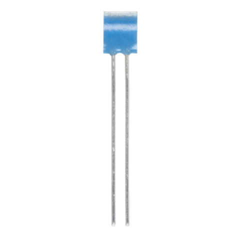
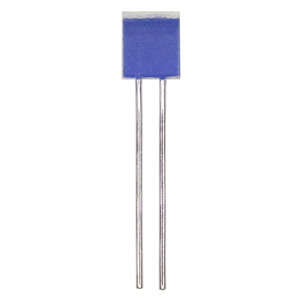
The MB219 platinum RTD temperature sensor range provides compact wired sensing elements for large-volume equipment and sensor programmes. Engineers can select Pt100 or Pt1000 nominal resistance according to the measurement circuit and required signal level. Standard MB219 variants use a 3850 ppm/K temperature coefficient and comply with DIN EN IEC 60751, while the separate Pt1000 version uses a 3750 ppm/K curve based on the same standard. The declared tolerance classes remain valid during continuous operation from -70 °C to +500 °C, with temporary exposure permitted up to +550 °C.
Nickel-wire leads are suitable for brazing, welding or crimping into probes and other assemblies. Defined response-time, self-heating, stability, vibration and shock data assist with system design and qualification. Typical applications include pyrolytic ovens, HVAC equipment and industrial temperature monitoring. Automotive use may be considered after confirming project-specific qualification and documentation requirements such as IMDS or PPAP.
Range features
A high level overview of what this range offers
- -70 °C to +500 °C continuous range: Covers low-temperature monitoring and elevated-temperature process applications.
- Temporary operation up to +550 °C: Accommodates qualified short-term thermal excursions above the continuous limit.
- Pt100 and Pt1000 options: Supports different excitation currents, signal levels and analogue front-end designs.
- 3850 and 3750 ppm/K variants: Allows the sensor curve to be matched to the measurement electronics.
- Defined response-time data: Provides a basis for modelling temperature-control and monitoring behaviour.
- Nickel-wire leads: Permit brazed, welded or crimped connections within sensor assemblies.
- Vibration and shock ratings: Provide mechanical design data for equipment exposed to movement or impact.
- Controlled long-term drift: Helps maintain the declared tolerance following extended high-temperature storage.
- Compact wired body: Supports installation in small probes and restricted sensing locations.
- Minimum 24-month storage life: Supports planned production when retained in the original packaging.
What’s in this range?
All the variants in the range and a comparison of what they offer
General specifications
| Specification | MB series RTD sensors |
|---|---|
Product type | Wired platinum resistance temperature detector |
Series | MB219 and MB219 TCR 3750 |
Continuous temperature range | -70 °C to +500 °C |
Temporary temperature exposure | Up to +550 °C |
Nominal resistance at 0 °C | Pt100 or Pt1000, depending on variant |
Temperature coefficient | 3850 ppm/K or 3750 ppm/K |
Standard relationship | 3850 ppm/K versions according to DIN EN IEC 60751; 3750 ppm/K version based on DIN EN IEC 60751 |
Tolerance classes | F 0.3 (B) or F 0.6 (2B), depending on variant |
Tolerance-class operating range | -70 °C to +500 °C during continuous operation |
Nominal-resistance measuring point | 6 mm from the end of the sensor body |
Pt100 measuring current | 0.3 to 1 mA |
Pt1000 measuring current | 0.1 to 0.3 mA |
Response in water | t0.5 = 0.05 s and t0.9 = 0.15 s at 0.4 m/s |
Response in air | t0.5 = 3 s and t0.9 = 10 s at 2 m/s |
Self-heating | 0.4 K/mW at 0 °C |
Insulation resistance at 20 °C | Greater than 100 MΩ |
Insulation resistance at 500 °C | Greater than 2 MΩ |
Long-term stability | R₀ drift after 1,000 hours in air at the declared upper limit does not exceed the applicable tolerance-class value |
Vibration resistance | At least 40 g acceleration from 10 to 2,000 Hz; installation-dependent |
Shock resistance | At least 100 g acceleration with an 8 ms half-sine pulse; installation-dependent |
Lead material | Nickel wire |
Lead tensile strength | At least 8 N |
Connection methods | Brazing, welding and crimping |
Standard packaging | Plastic bag; alternatives available on request |
Storage life | Minimum 24 months in the original packaging |
Safety information | California Proposition 65 warning applies for potential exposure to lead oxide, cobalt oxide, nickel and cobalt |
Variant comparison
| Specification | MB219 Pt100 | MB219 Pt1000 | MB219 TCR 3750 Pt1000 |
|---|---|---|---|
Order number | 5202785 | 5190184 | 5202783 |
Style | Wired | Wired | Wired |
Nominal resistance R₀ | Pt100 | Pt1000 | Pt1000 |
Temperature coefficient | 3850 ppm/K | 3850 ppm/K | 3750 ppm/K |
Tolerance class | F 0.3 (B) | F 0.3 (B) | F 0.6 (2B) |
Body length | 2.1 mm +0.3/-0.1 mm | 2.1 mm +0.3/-0.1 mm | 2.1 mm +0.3/-0.1 mm |
Body width | 1.9 mm ±0.3 mm | 1.9 mm ±0.3 mm | 1.9 mm ±0.3 mm |
Body height | 0.9 mm +0.3/-0.25 mm | 0.9 mm +0.3/-0.25 mm | 0.9 mm +0.3/-0.25 mm |
Lead length | 7 mm ±1 mm | 7 mm ±1 mm | 7 mm ±1 mm |
Measuring current | 0.3 to 1 mA | 0.1 to 0.3 mA | 0.1 to 0.3 mA |
Connection methods | Brazing, welding or crimping | Brazing, welding or crimping | Brazing, welding or crimping |
Self-heating at 0 °C | 0.4 K/mW | 0.4 K/mW | 0.4 K/mW |
Temperature range | -70 °C to +500 °C | -70 °C to +500 °C | -70 °C to +500 °C |
Packaging | Plastic bag | Plastic bag | Plastic bag |
FAQs
for MB series RTD sensors
The choice depends on the resistance level, TCR curve and tolerance class required by the measurement circuit. Standard MB219 variants are available as Pt100 or Pt1000 with a 3850 ppm/K coefficient and class F 0.3 (B), while the MB219 TCR 3750 is a Pt1000 device with class F 0.6 (2B). Pt100 is specified for a measuring current of 0.3 to 1 mA, whereas both Pt1000 versions use 0.1 to 0.3 mA. The higher nominal resistance can produce a larger signal voltage at the same excitation current, but the analogue front end must match the selected resistance and curve. The 3750 and 3850 ppm/K variants should not be interchanged without updating the conversion coefficients or calibration.
Keep the excitation current within the specified range and calculate the resulting sensor power at the resistance expected during operation. The self-heating figure is 0.4 K/mW at 0 °C, so dissipation can be estimated using P = I²R. At 0 °C, a Pt100 element at 1 mA dissipates 0.1 mW, corresponding to approximately 0.04 K under the stated condition; a Pt1000 element at 0.3 mA dissipates 0.09 mW, or approximately 0.036 K. These are calculated reference values rather than guaranteed system errors because thermal coupling and airflow affect the resulting temperature rise. Use the lowest current that provides an adequate signal-to-noise ratio and verify the assembled sensor under representative conditions.
No, the declared tolerance class is valid for continuous operation from -70 °C to +500 °C. Exposure up to +550 °C is identified as temporary, but a duration and tolerance class at that temperature are not defined, so it should not be treated as an indefinite operating point. For long-term stability, R₀ drift after 1,000 hours in air at the upper declared continuous limit does not exceed the tolerance of the applicable class. The sensor body may tolerate the stated range while joints, cable insulation, potting materials and probe hardware impose lower limits. Set the complete assembly rating according to its least temperature-resistant component and qualify any excursion above +500 °C separately.
The component is rated for at least 40 g acceleration over a vibration range of 10 to 2,000 Hz. Its shock rating is at least 100 g with an 8 ms half-sine pulse, while the nickel-wire leads have a tensile-strength rating of at least 8 N. Both vibration and shock performance depend on the way the element is installed, so these values should not be treated as unconditional ratings for a finished probe. Unsupported leads, rigid joints and local stress at the sensor body can alter the result within the complete assembly. Validate the mounted sensor using the vibration, shock and thermal-cycling profiles that apply to the final equipment.
The nickel-wire leads are intended for brazing, welding or crimping. Conventional soldering is not included among the specified connection methods, so it should not be assumed suitable without a separately qualified process. The standard lead length is 7 mm ±1 mm, giving the assembly process limited space for joining and strain relief. Choose the connection method according to the joint geometry, process temperature and mechanical loading, then verify resistance shift and joint integrity after assembly. Alternative wire lengths and resistance values may be requested when the standard construction does not suit the intended probe design.
Response depends strongly on the surrounding medium, its flow rate and the thermal mass added by the finished assembly. In water moving at 0.4 m/s, the specified values are t0.5 = 0.05 seconds and t0.9 = 0.15 seconds. In air moving at 2 m/s, the corresponding values are 3 seconds and 10 seconds. The t0.5 and t0.9 figures indicate the time required to reach 50% and 90% of the final response after a temperature change. A sleeve, adhesive, potting compound or thick probe wall can increase these times, so control-loop calculations should use measurements from the complete installed sensor.
The MB219 range may be considered for automotive use, but the standard catalogue variants should not automatically be treated as automotive-qualified components. Additional project requirements, including IMDS or PPAP documentation, can be evaluated as part of the selection process. No AEC-Q200 qualification is stated for the listed variants, and the vibration and shock ratings remain dependent on installation. Engineers should therefore review the complete environmental, traceability and documentation requirements rather than relying on the temperature range alone. Confirm the required deliverables and component status before releasing the sensor for an automotive production design.