L and LN series RTD sensors
- Technology
- Platinum RTD sensors
- Partner
- YAGEO Nexensos GmbH
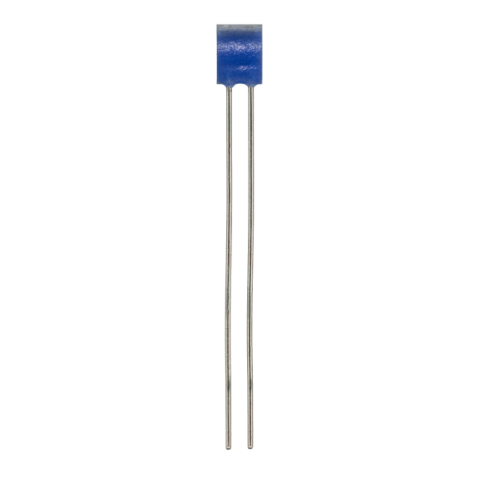
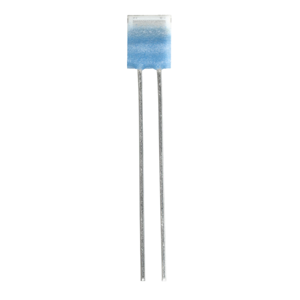
The L and LN series RTD sensors from YAGEO Nexensos are designed for resistance-based temperature measurement in applications where reliable, repeatable temperature monitoring is essential. RTDs (Resistance Temperature Detectors) measure temperature through the predictable change in electrical resistance of a sensing element, making them suitable for integration into industrial equipment, monitoring systems and temperature probes.
The L series offers a range of compact, wired platinum resistance sensors, including the L220, L416, L420, L1020 and L220 P. With Pt100 and Pt1000 options, several tolerance classes and different body dimensions, the series provides flexibility for a variety of temperature measurement designs. Its platinum sensing characteristic follows DIN EN IEC 60751, with a temperature coefficient of 3850 ppm/K. AgPd leads and soft-solder connections help simplify integration into probes, sleeves and measurement circuits, while the perpendicular wire arrangement of the L220 P supports specialised installation requirements.
The LN series is intended for resistance-based temperature sensing, but its model-specific specifications should be confirmed against the relevant datasheet before selection. Together, the L and LN families offer a starting point for designers seeking RTD solutions that can be matched to their measurement accuracy, installation and connection requirements.
Range features
A high level overview of what this range offers
- Reliable platinum RTD technology – Provides a predictable relationship between temperature and electrical resistance for accurate, repeatable temperature measurement.
- DIN EN IEC 60751 compliance – Features a standard platinum resistance characteristic with a temperature coefficient of 3850 ppm/K, simplifying integration into compatible measurement systems.
- Pt100 and Pt1000 options – Offers nominal resistance values of 100 Ω and 1,000 Ω, allowing flexibility to suit different measurement circuits and application requirements.
- Multiple tolerance classes – Available in F 0.1 (1/3 B), F 0.15 (Class A) and F 0.3 (Class B) options, supporting a range of accuracy and cost requirements.
- Compact sensor design – With body lengths ranging from approximately 2.3 mm to 9.5 mm, the L series is suitable for space-constrained installations and compact temperature probes.
- Wired design for easy integration – AgPd leads and soft-solder connections support straightforward assembly into temperature probes, protective sleeves and measurement circuits.
- Flexible connection orientation – The L220 P features perpendicular connection wires, providing greater flexibility for probe-end installations and specialised assembly designs.
- Versatile application suitability – Ideal for temperature monitoring in HVAC systems, energy management, food and beverage machinery, medical equipment and industrial applications.
Downloads
for L and LN series RTD sensors
What’s in this range?
All the variants in the range and a comparison of what they offer
Range specifications
| Parameter | L series | LN series |
|---|---|---|
Sensor technology | Platinum resistance temperature detector (Pt-RTD) | Platinum resistance temperature detector (Pt-RTD) |
Product variants | L220, L416, L420, L1020, L220 P | LN222 |
Construction | Wired sensor element | Wired sensor element |
Characteristic standard | DIN EN IEC 60751 | DIN EN IEC 60751 |
Nominal resistance | Pt100 and Pt1000, depending on variant | Pt100 or Pt1000, depending on variant |
Temperature coefficient | 3850 ppm/K | 3850 ppm/K |
Continuous operating range | −50 °C to +400 °C, depending on variant and tolerance class | −50 °C to +300 °C for Class A; −50 °C to +400 °C for Class B |
Available tolerance classes | F 0.1 (1/3 B), F 0.15 (A), F 0.3 (B), depending on variant | F 0.15 (A), F 0.3 (B) |
Connection technology | Soft soldering | Soldering; confirm process limits in the applicable datasheet |
Lead material | AgPd | Confirm against the applicable datasheet |
Packaging | VCI plastic bag | VCI plastic bag |
Variant comparison
| Specification | L220 | L416 | L420 | L1020 | L220 P | LN222 |
|---|---|---|---|---|---|---|
Nominal resistance | Pt100 or Pt1000 | Pt100 | Pt1000 | Pt1000 | Pt100 | Pt100 or Pt1000 |
Available tolerance classes | F 0.1, F 0.15, F 0.3 | F 0.15, F 0.3 | F 0.1, F 0.15, F 0.3 | F 0.1, F 0.15, F 0.3 | F 0.3 | F 0.15, F 0.3 |
F 0.1 continuous range | 0 to +150 °C | — | 0 to +150 °C | −50 to +150 °C | — | — |
F 0.15 continuous range | −50 to +300 °C | −50 to +300 °C | −50 to +300 °C | −50 to +300 °C | — | −50 to +300 °C |
F 0.3 continuous range | −50 to +400 °C | −50 to +400 °C | −50 to +400 °C | −50 to +400 °C | −50 to +400 °C | −50 to +400 °C |
Body length L | 2.4 mm (+0.2/−0.1) | 3.9 mm (+0.2/−0.1) | 3.9 mm (±0.15) | 9.5 mm (±0.15) | 2.3 mm (±0.2) | 2.3 mm (+0.2/−0.1) |
Body width W1 | 1.9 mm (±0.2) | 1.5 mm (±0.2) | 1.9 mm (±0.2) | 1.9 mm (±0.2) | 2.0 mm (±0.2) | 2.1 mm (±0.2) |
Body height H | 1.0 mm (+0.3/−0.2) | 1.0 mm (+0.3/−0.2) | 1.0 mm (+0.3/−0.2) | 1.0 mm (+0.3/−0.2) | 1.4 mm (±0.3) | 0.9 mm (+0.3/−0.2) |
Lead length LL | 10 mm (±1.0) | 10 mm (±1.0) | 10 mm (±1.0) | 10 mm (±1.0) | 10 mm (±1.0) | 10 mm (±1.0) |
Lead diameter Lø | 0.25 mm (±0.02) | 0.25 mm (±0.02) | 0.25 mm (±0.02) | 0.25 mm (±0.02) | 0.25 mm (±0.02) | 0.22 mm (±0.02) |
Width W2 | 0.8 mm (±0.1) | 0.7 mm (±0.1) | 0.8 mm (±0.1) | 0.9 mm (±0.1) | 0.8 mm (±0.1) | 0.8 mm (±0.1) |
Self-heating at 0 °C | 0.4 K/mW | 0.4 K/mW | 0.3 K/mW | 0.2 K/mW | 0.4 K/mW | 0.4 K/mW |
Water response t₀.₅ / t₀.₉ at 0.4 m/s | 0.06 / 0.20 s | 0.07 / 0.25 s | 0.08 / 0.25 s | 0.12 / 0.30 s | 0.20 / 0.30 s | 0.05 / 0.15 s |
Air response t₀.₅ / t₀.₉ at 2 m/s | 3 / 13 s | 3.2 / 14 s | 3.5 / 15 s | 6 / 20 s | 3 / 9 s | 3 / 10 s |
Measuring current | Pt100: 0.3–1 mA; Pt1000: 0.1–0.3 mA | 0.3–1 mA | 0.1–0.3 mA | 0.1–0.3 mA | 0.3–1 mA | Pt100: 0.3–1 mA; Pt1000: 0.1–0.3 mA |
Lead arrangement | Standard wired element | Standard wired element | Standard wired element | Standard wired element | Perpendicular to substrate | Wired element; lead forming may vary |
Lead material | AgPd | AgPd | AgPd | AgPd | AgPd | Nickel-silver-coated |
Connection technology | Soft soldering | Soft soldering | Soft soldering | Soft soldering | Soft soldering | Crimping and soft soldering |
Order numbers | See L220 catalogue entries | See L416 catalogue entries | See L420 catalogue entries | See L1020 catalogue entries | See L220 P catalogue entries | 32207770, 32207771, 32207772, 32207773 |
Packaging | VCI plastic bag | VCI plastic bag | VCI plastic bag | VCI plastic bag | VCI plastic bag | VCI plastic bag |
FAQs
for L and LN series RTD sensors
Choose the variant according to nominal resistance, package geometry, lead orientation and acceptable thermal response. L220 is the only listed variant offering both Pt100 and Pt1000, with a 2.4 mm nominal body length and 0.4 K/mW self-heating. L416 uses Pt100 in a 3.9 × 1.5 mm body, while L420 uses Pt1000 in a 3.9 × 1.9 mm body; their water t₀.₉ values are both 0.25 seconds. L1020 is the 9.5 mm Pt1000 format with 0.2 K/mW self-heating, whereas L220 P uses Pt100 and places its leads perpendicular to the substrate. Begin with the electrical interface, then confirm the available installation volume and required lead direction.
Select Pt100 or Pt1000 according to the measurement circuit, cable arrangement and acceptable influence of lead resistance. Both use a temperature coefficient of 3850 ppm/K, but Pt1000 has ten times the nominal resistance of Pt100 at 0 °C, reducing the percentage contribution of external lead and contact resistance in a two-wire circuit. The recommended current is 0.3 to 1 mA for Pt100 and 0.1 to 0.3 mA for Pt1000. L220 supports either value, while L416 and L220 P are Pt100 and L420 and L1020 are Pt1000. The final choice should match the analogue front end, excitation source and compensation method planned for the system.
The selected tolerance class determines both the permitted resistance deviation and the continuous temperature interval over which that class applies. Class F 0.3 (B) is available across all five variants and covers −50 °C to +400 °C. Class F 0.15 (A) covers −50 °C to +300 °C on L220, L416, L420 and L1020. Class F 0.1 (1/3 B) is limited to 0 °C to +150 °C on L220 and L420, while the L1020 version extends from −50 °C to +150 °C. Engineers should therefore specify the class and temperature interval together rather than selecting an order number from the class designation alone.
Element-level response depends strongly on the surrounding medium, flow speed and mechanical construction around the sensor. In water flowing at 0.4 m/s, t₀.₅ values range from 0.06 seconds for L220 to 0.20 seconds for L220 P, while t₀.₉ remains between 0.20 and 0.30 seconds. In air flowing at 2 m/s, t₀.₅ ranges from 3 to 6 seconds and t₀.₉ from 9 to 20 seconds. These figures apply to the sensor element under defined test conditions rather than to a completed probe. Encapsulation, sleeve wall thickness, thermal compound, air gaps and mounting pressure should therefore be included when validating the response of the final assembly.
Keep the excitation current within the stated range and calculate I²R power at the highest resistance expected in the application. At 0 °C, a Pt100 element driven at 1 mA dissipates approximately 0.1 mW; with 0.4 K/mW self-heating, this indicates an element-level temperature rise of roughly 0.04 K under the reference condition. A Pt1000 element at 0.3 mA dissipates approximately 0.09 mW, corresponding to about 0.036 K for L220, 0.027 K for L420 or 0.018 K for L1020. Actual temperature rise varies with medium, airflow, mounting and operating temperature. Lower continuous current or controlled pulsed excitation can be considered where measurement uncertainty is sensitive to self-heating.
The elements have defined vibration, shock and lead-strength figures, but their installed capability depends on the surrounding assembly. Each variant is specified for at least 40 g acceleration from 10 to 2,000 Hz and at least 100 g acceleration with an 8 ms half-sine shock pulse. The AgPd connection leads have a tensile strength of at least 8 N. These figures should not be treated as complete probe ratings because unsupported leads, rigid encapsulation and resonant structures can alter the stress applied to the ceramic element. Appropriate strain relief, controlled lead forming and application-level vibration and shock testing are therefore required before production release.
Use a soft-soldering process compatible with the AgPd leads and the operating temperature of the selected solder alloy. A universal soldering profile is not defined for the range, so dwell time, heat transfer and lead forming should be qualified within the intended assembly process. The nominal-resistance measuring point is located 8 mm from the end of the sensor body, which should be considered during incoming inspection and resistance verification. Storage life is at least 12 months after manufacture under the recommended conditions, with a nitrogen atmosphere recommended. Batch-dependent V-shaped bending of the connection wires can occur after sample measurement, but it does not affect the function of the platinum measuring element.