Low-Noise Fibre Lasers
- Technology
- Fibre lasers
- Partner
- CNI
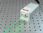
The Low-Noise Fibre Laser Range is intended for optical systems where amplitude fluctuations and beam drift need to be controlled. The portfolio covers wavelengths from 360 to 1550 nm, although these wavelengths are not mapped to named fibre-laser models. Application areas include DNA sequencing, cell sorting, spectrum analysis, interference measurement, holography, photo processing and biomedical instrumentation. Range-level beam data includes TEM00 operation and M² below 1.1, supporting predictable propagation and focusing in compatible configurations.
Noise-related figures include relative intensity noise below 0.05%, RMS noise stability below 0.2% over four hours and a stated measurement bandwidth from 20 Hz to 20 MHz. Power stability is specified below 0.5%, while available pointing figures include less than 5 µrad/°C and less than 50 µrad under separately defined conditions. As no part numbers or model tables are provided, wavelength-specific power, dimensions, interfaces and exact performance assignments must be confirmed for the selected configuration.
Range features
A high level overview of what this range offers
- 360–1550 nm low-noise wavelength coverage – Supports source selection across ultraviolet, visible and infrared optical systems.
- Noise-conscious resonant-cavity design – Can reduce amplitude fluctuation associated with competition between cavity modes.
- TEM00 beam mode – Provides a fundamental spatial profile for controlled focusing and propagation.
- M² below 1.1 – Supports near-Gaussian beam delivery in compatible configurations.
- Relative intensity noise below 0.05% – Helps limit intensity fluctuation within sensitive measurement chains.
- Power stability below 0.5% – Supports repeatable optical output during extended operation.
- RMS noise stability below 0.2% over four hours – Provides a reference for applications sensitive to long-term drift.
- Defined pointing-stability figures – Values below 5 µrad/°C and below 50 µrad assist thermal and alignment planning.
- 20 Hz to 20 MHz noise bandwidth – Provides a defined frequency window for compatible noise measurements.
What’s in this range?
All the variants in the range and a comparison of what they offer
| Parameter | Value | Conditions or notes |
|---|---|---|
Low-noise wavelength coverage | 360–1550 nm | Fibre-laser variant mapping is not provided |
Beam spot pattern | TEM00 | Range-level characteristic |
Beam quality | M² < 1.1 | Listed in both feature groups |
Temperature-normalised pointing stability | < 5 µrad/°C | Model assignment is not defined |
Constant-temperature noise | -52 dB | At 23 ± 3 °C; measurement definition is not given |
Noise stability | < 0.2% RMS | Four-hour measurement period |
Noise measurement bandwidth | 20 Hz to 20 MHz | Associated with the first feature group |
Power stability | < 0.5% | Associated with the second feature group |
Relative intensity noise | < 0.05% | Associated with the second feature group |
Pointing stability | < 50 µrad | Measurement conditions are not defined |
The two feature groups are not mapped to named models. Do not assume that every figure applies simultaneously to one fibre-laser configuration; check each selected model against its model-specific technical documentation.
FAQs
for Low-Noise Fibre Lasers
The figures should be treated as range-level indicators rather than values that automatically apply to every wavelength or configuration. Available performance data includes constant-temperature noise of -52 dB at 23 ± 3 °C, RMS noise stability below 0.2% over four hours, power stability below 0.5% and relative intensity noise below 0.05%. One noise bandwidth is specified as 20 Hz to 20 MHz, so comparisons are valid only when detector bandwidth, filtering, averaging time and environmental conditions are aligned. The -52 dB and percentage figures use different formats and should not be converted or compared without the underlying measurement definitions. Final approval should use model-specific test conditions matched to the instrument’s actual detection bandwidth.
The available low-noise range spans 360 to 1550 nm, covering ultraviolet, visible and infrared operation. Wavelength should first be matched to the sample’s absorption or fluorescence response, detector sensitivity, optical coating range and any fibre or free-space components in the beam path. Listed applications include DNA sequencing, cell sorting, spectrum analysis, interference measurement, holography, photo processing and biomedical systems, but the preferred wavelength will differ between these uses. Output power and exact fibre-laser model availability are not mapped by wavelength. Engineers should therefore select the wavelength first, then confirm power, linewidth, polarisation and output interface for the chosen configuration.
TEM00 operation and M² below 1.1 indicate a near-fundamental spatial mode and a beam that is close to ideal Gaussian propagation. This can support predictable focusing, collimation and spatial filtering while reducing the influence of higher-order mode content on the optical layout. It may also assist coupling into a compatible optical fibre, although coupling efficiency depends on numerical aperture, mode-field diameter, alignment and the actual output interface. The beam-quality figure does not define beam diameter, divergence or astigmatism. Those parameters should be obtained for the selected wavelength before lens focal lengths, aperture sizes or fibre-coupling optics are finalised.
Two pointing figures are provided: below 5 µrad/°C and below 50 µrad. They appear to represent different conditions because the first is normalised to temperature, while the second is presented as an absolute angular value. These figures should not be treated as directly interchangeable without knowing the measurement period, temperature profile, mounting arrangement and reference distance. Over a long beam path, even a small angular change can move the spot at an aperture, detector or interferometer input. The installation should therefore use a stable mount and controlled thermal environment, followed by an acceptance test at the actual propagation distance.
Noise performance should be compared over the same frequency window, and 20 Hz to 20 MHz is the stated bandwidth for one range-level measurement. A detector or acquisition chain with a narrower bandwidth may report lower integrated noise, while a wider or differently filtered chain can produce another result. Relative intensity noise below 0.05%, RMS stability below 0.2% over four hours and the -52 dB figure therefore describe different measurement views rather than one interchangeable specification. A testing example also refers to RMS performance over two hours across 20 Hz to 20 MHz. Engineers should document detector type, electrical bandwidth, sampling, filtering and averaging before comparing candidate lasers.
One noise figure is associated with a constant-temperature condition of 23 ± 3 °C, and a separate testing example covers temperatures from 10 to 35 °C. Thermal conditions therefore form part of the noise and pointing assessment rather than being incidental to it. A laboratory or instrument enclosure should minimise rapid ambient changes, airflow over the laser head and heat transfer from nearby electronics. Warm-up time, heat-sinking and permissible baseplate temperature are not defined, so they should be established during model-specific qualification. For production equipment, acceptance testing should reproduce the intended operating temperature range while monitoring both optical power and beam position.
Model approval requires more than the available range-level noise and beam-quality figures. Part numbers, output power, linewidth, wavelength tolerance, polarisation, beam diameter, divergence, electrical input, cooling method, modulation capability, dimensions, connectors, laser class and approvals are not identified. These parameters affect detector saturation, spectral resolution, mechanical integration, thermal design, safety controls and compatibility with the intended optics. The two feature groups also lack a model mapping, so their values cannot be assigned confidently to a particular variant. A procurement specification should therefore require model-specific technical data and defined test conditions before design freeze or purchase.