High density stack (HDS) laser diode packaging
- Technology
- DPSS lasers
- Partner
- Cutting Edge Optronics (CEO)
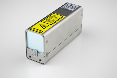
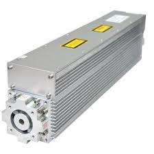
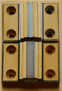
The HDS high-density QCW laser diode array is a compact stacked emitter for pulsed systems requiring high optical intensity from a small area. Closely spaced diode bars provide power densities approaching 25 kW/cm². Standard wavelengths span 780–980 nm, while custom wavelength configurations can address application-specific optical requirements. The range supports 1–20 bars, peak array output from 400 to 4,000 W and bar emission lengths from 3 to 10 mm.
Typical applications include LIDAR, laser rangefinding, laser-induced breakdown spectroscopy, materials processing and diode-pumped solid-state lasers. HDS assemblies can be configured on G, A, Cs, Derringer and Shooter package platforms, allowing the mechanical and cooling interface to be selected around the system design. Conductively cooled and water-cooled configurations are available. Mini-bar versions below 1 cm accommodate restricted mechanical and optical envelopes.
Range features
A high level overview of what this range offers
- Power density approaching 25 kW/cm²: Concentrates high peak optical power within a small emitting area.
- 400–4,000 W peak QCW output: Supports pulsed-system sizing across several output levels.
- 780–980 nm standard wavelength range: Enables matching to pumping, sensing and materials-processing requirements.
- Custom wavelength configurations: Accommodate optical systems with application-specific wavelength requirements.
- 1–20 bars at 150 µm pitch: Provides dense stacked emission with a selectable bar count.
- 3–10 mm bar emission length: Offers geometry options for different optical layouts.
- Mini-bars below 1 cm: Fit restricted mechanical and optical envelopes.
- Hard solder and expansion-matched materials: Support material compatibility through thermal cycling.
- Multiple package platforms: Enable integration with G, A, Cs, Derringer and Shooter layouts.
- 55% typical conversion efficiency at 25 °C: Provides a defined basis for electrical and thermal sizing.
- 33° × 6° FWHM divergence: Supports axis-specific collection and beam-shaping design.
What’s in this range?
All the variants in the range and a comparison of what they offer
| Typical parameter at 25 °C | Typical value | Unit |
|---|---|---|
Wavelength | 780–980 | nm |
Operating mode | QCW | — |
Array peak output power | 400–4,000 | W |
Bar emission length | 3–10 | mm |
Number of bars | 1–20 | bars |
Operating current | 170 | A |
Operating voltage per bar | 1–2 | V |
Power-conversion efficiency | 55 | % |
Bar-to-bar pitch | 150 | µm |
Pulse width | 300 maximum | µs |
Duty cycle | 5 maximum | % |
Beam divergence, FWHM | 33 × 6 | ° |
FAQs
for High density stack (HDS) laser diode packaging
The HDS range is intended for quasi-continuous-wave operation rather than unrestricted continuous-wave use. Typical operation is 170 A at 1–2 V per bar, with a maximum pulse width of 300 µs and a maximum duty cycle of 5% at 25 °C. Driver timing must therefore keep pulse width multiplied by repetition rate within the duty-cycle limit while controlling current overshoot. These limits indicate that the array is designed around high peak power from 400 to 4,000 W rather than continuous average output. A CW or higher-duty application requires a separately defined package and thermal operating envelope rather than an extrapolation of the QCW ratings.
Selection should begin with the required peak optical power and emitting geometry, using bar count as a configuration variable. The range covers 1–20 bars, 400–4,000 W peak output, bar emission lengths of 3–10 mm and a 150 µm bar-to-bar pitch. These figures define the available operating envelope but do not establish a fixed output value for every possible bar count and wavelength. Increasing the bar count also affects the electrical and thermal design because voltage is stated per bar and each bar contributes heat during a pulse. The exact bar count, output, wavelength, package platform and cooling method should therefore be fixed before releasing the driver, optics or mechanical design.
The wavelength should be selected against the optical process, gain medium, detector response and permitted tolerance of the complete system. Standard configurations span 780–980 nm, with custom wavelengths also available for DPSSL crystal end pumping, LIDAR, LIBS, laser rangefinding and materials processing. For crystal pumping, the chosen wavelength must coincide with the absorption band used by the laser medium; for sensing applications, source, target and detector performance must be considered together. Spectral width, wavelength tolerance and temperature coefficient are not defined for the range. These parameters should be agreed for the selected configuration before finalising filters, coatings, detectors or pump-crystal thermal control.
Cooling and mechanical integration depend on the selected HDS package configuration. Conductively cooled configurations are available, and the stack can also be applied to G, A, Cs, Derringer and Shooter platforms, with Shooter using water cooling. A typical conversion efficiency of 55% means that thermal design remains important even though operation is limited to a 5% duty cycle. Hard solder and expansion-matched materials are used within the assembly to address material compatibility through temperature changes. The mounting face, electrical terminals, cooling path and permitted interface temperature should be resolved for the chosen platform before enclosure and cold-plate drawings are released.
The stated beam divergence is 33° × 6° at full width at half maximum, so the native output is strongly asymmetric. Collection and beam-shaping optics must therefore be designed separately for the two orthogonal axes rather than treating the emitter as a circular source. The optical design must also accommodate a bar emission length of 3–10 mm and a dense 150 µm bar pitch across stacks containing up to 20 bars. FWHM is not the full angular extent of the emission, so aperture sizing should include an appropriate margin beyond the quoted divergence. The final optical train should be checked against the selected bar length, stack count and working distance to avoid clipping or uneven pump distribution.
The driver must deliver high-current QCW pulses with controlled timing and a stable current plateau. The typical operating current is 170 A, while the operating voltage is 1–2 V per bar across configurations containing 1–20 bars. Because voltage is specified per bar, the total supply requirement depends on the electrical interconnection used in the selected package and should not be inferred from bar count alone. Pulse width must remain at or below 300 µs and duty cycle at or below 5%, with switching behaviour managed to limit overshoot and ringing. Package-specific terminal details, inductance, polarity and interlock requirements should be confirmed before finalising the driver output stage and energy-storage network.
The 55% figure should be treated as a typical electrical-to-optical conversion value at 25 °C rather than a guaranteed efficiency for every wavelength, bar count or pulse condition. At that efficiency, approximately 45% of the electrical input is not converted into optical output and must be considered in the thermal model. As an illustration, 4,000 W of optical peak power would correspond to about 7.27 kW of electrical input and 3.27 kW of non-optical peak power if the same efficiency applied at that operating point. Duty cycle reduces average heat but does not remove short-duration temperature gradients within the stack. Cooling capacity, pulse repetition rate and transient thermal behaviour should therefore be evaluated together for the final configuration.