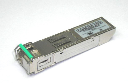
CT-0622TSP-MB5L-E 1310 nm FP 15 km 622 Mb/s SFP Transceiver w. DDMI
- Technology
- Optical transceivers
- Partner
- Coretek
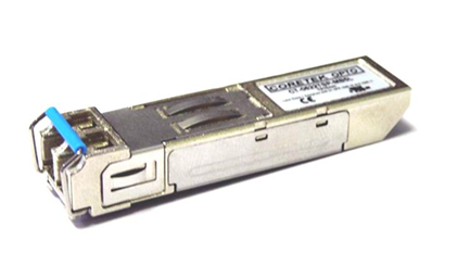
The CT-0622TSP-MB5L-E SFP transceiver is designed for 622 Mb/s ATM/SONET OC-12 and SDH STM-4 optical links. Its 1310 nm Fabry–Pérot laser supports transmission over 9/125 µm single-mode fibre across a specified distance of 15 km. The module uses a duplex LC receptacle and follows the SFP Multi-Source Agreement for integration into compatible pluggable host interfaces. Digital diagnostic monitoring is accessible through the two-wire I²C interface defined by SFF-8472. A 3.1 to 3.5 V operating range suits equipment built around a nominal 3.3 V supply rail. The −40 °C to +85 °C case temperature range supports deployment in equipment subject to wide internal temperature variation. Typical applications include telecommunications transport equipment, single-mode fibre links and optical-to-electrical interface conversion.
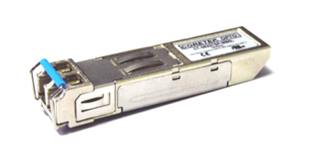
Range features
A high level overview of what this range offers
- 622 Mb/s NRZ operation: Matches ATM/SONET OC-12 and SDH STM-4 interfaces.
- 1310 nm FP laser with 15 km reach: Supports intermediate-distance links over 9/125 µm single-mode fibre.
- −28 dBm receiver sensitivity: Provides a 13 dB worst-case optical budget when paired with the −15 dBm minimum launch power.
- SFP MSA form factor: Supports integration into compatible pluggable host cages.
- Duplex LC receptacle: Provides separate transmit and receive connections in a compact optical interface.
- SFF-8472 DDMI over I²C: Enables host access to module identification and diagnostic information.
- −40 °C to +85 °C case range: Accommodates equipment with a wide internal operating temperature range.
- 3.1 to 3.5 V supply range: Integrates with nominal 3.3 V host power systems.
- TX Disable, TX Fault and RX_LOS signals: Support transmitter control, fault reporting and optical link-state monitoring.
- Class 1 laser and lead-free construction: Addresses the stated eye-safety and material requirements.
Downloads
for CT-0622TSP-MB5L-E 1310 nm FP 15 km 622 Mb/s SFP Transceiver w. DDMI
What’s in this range?
All the variants in the range and a comparison of what they offer
Specifications
| Category | Parameter | Value | Condition or standard |
|---|---|---|---|
General | Product identifier | CT-0622TSP-MB5L-E | SFP optical transceiver |
General | Data rate | 622 Mb/s | NRZ signalling |
General | Specified link distance | 15 km | Single-mode fibre |
General | Fibre type | 9/125 µm single-mode | Optical power measured when coupled into this fibre type |
General | Optical connector | Duplex LC | Separate transmit and receive paths |
General | Form factor | SFP | Multi-Source Agreement compatible |
General | Electrical interface | AC/AC differential | Transmit and receive data paths |
General | Signal-detect output | TTL | Product coding information |
Applications | Network interfaces | ATM/SONET OC-12; SDH STM-4 | 622 Mb/s links |
Diagnostics | Digital diagnostics | SFF-8472 DDMI | Two-wire I²C serial interface |
Operating conditions | Case operating temperature, TA | −40 to +85 °C | Extended-temperature range |
Operating conditions | Supply voltage, VCC | 3.1 to 3.5 V | 3.3 V nominal system |
Operating conditions | Data input voltage swing, VID | 400 to 1,660 mV | Differential input |
Absolute maximum | Storage temperature, TS | −40 to +85 °C | Absolute maximum rating |
Absolute maximum | Supply voltage, VCC | 0 to 6 V | Absolute maximum rating |
Absolute maximum | Data input voltage | 0 V to VCC | Absolute maximum rating |
Transmitter electrical | Supply current, ICCT | 200 mA maximum | Transmitter section |
Transmitter electrical | TX Disable input low, VIL | 0 to 0.8 V | Logic low |
Transmitter electrical | TX Disable input high, VIH | 2.0 V to VCC | Logic high |
Transmitter electrical | TX Fault output low, VOL | 0 to 0.8 V | Logic low |
Transmitter electrical | TX Fault output high, VOH | 2.0 V to VCC | Logic high |
Receiver electrical | Supply current, ICCR | 100 mA maximum | Receiver section |
Receiver electrical | Data output differential voltage, VOD | 0.4 to 1.3 V | Differential output |
Receiver electrical | RX_LOS output low, VOL | 0 to 0.8 V | Logic low |
Receiver electrical | RX_LOS output high, VOH | 2.0 V to VCC | Logic high |
Serial interface | MOD_DEF low level, VIL | −0.6 V to 0.3 × VCC | MOD_DEF(1) and MOD_DEF(2) |
Serial interface | MOD_DEF high level, VIH | 0.7 × VCC to VCC + 0.5 V | MOD_DEF(1) and MOD_DEF(2) |
Transmitter optical | Laser type | Fabry–Pérot laser diode | 1310 nm nominal wavelength |
Transmitter optical | Average optical output power, PO | −15 to −8 dBm | Coupled into 9/125 µm single-mode fibre |
Transmitter optical | Extinction ratio, ER | 8.2 dB minimum | |
Transmitter optical | Centre wavelength, λC | 1,275 to 1,355 nm | 1,310 nm typical |
Transmitter optical | RMS spectral width | 2.5 nm maximum | |
Transmitter optical | Optical rise time | 1.2 ns maximum | Measured from 20% to 80% |
Transmitter optical | Optical fall time | 1.2 ns maximum | Measured from 20% to 80% |
Transmitter optical | Output eye | ITU-T G.957 compliant | |
Receiver optical | Maximum input optical power | −3 dBm | Receiver overload level |
Receiver optical | Receiver sensitivity | −28 dBm | PRBS 2²³−1 at BER below 10⁻¹⁰ |
Receiver optical | Operating wavelength | 1,100 to 1,600 nm | |
Receiver optical | Loss-of-signal assert threshold, PA | −42 dBm | RX_LOS asserted |
Receiver optical | Loss-of-signal deassert threshold, PD | −27 dBm | RX_LOS deasserted |
Receiver optical | Loss-of-signal hysteresis | 0.5 dB | PD minus PA |
Timing | TX_DISABLE assertion time, t_off | 10 µs maximum | Transmitter shutdown |
Timing | TX_DISABLE negation time, t_on | 1 ms maximum | Transmitter activation |
Timing | Initialisation time, t_init | 300 ms maximum | Includes TX_FAULT reset |
Timing | TX_FAULT assertion time, t_fault | 100 µs maximum | Fault detection to assertion |
Timing | TX_DISABLE reset initiation, t_reset | 10 µs | Disable duration required to start reset |
Timing | RX_LOS assertion time | 100 µs maximum | Signal transition from present to absent |
Timing | RX_LOS deassertion time | 100 µs maximum | Signal transition from absent to present |
Safety | Laser classification | Class 1 | Designed to meet EN 60825-1 |
Materials | Substance requirements | RoHS-compliant and lead-free | |
Reliability | Characterisation basis | GR-468-CORE | Telcordia specification |
EMC | Emissions design target | FCC Class B limits | Final system compliance remains installation-dependent |
Pin assignments
| Pin | Symbol | Function |
|---|---|---|
1 | VeeT | Transmitter ground |
2 | TX Fault | Transmitter fault indication |
3 | TX Disable | Transmitter disable; a high level or open input disables the module |
4 | MOD-DEF(2) | Two-wire serial identification interface |
5 | MOD-DEF(1) | Two-wire serial identification interface |
6 | MOD-DEF(0) | Grounded within the module |
7 | Rate Select | Not connected |
8 | LOS | Loss-of-signal indication |
9 | VeeR | Receiver ground |
10 | VeeR | Receiver ground |
11 | VeeR | Receiver ground |
12 | RD− | Inverted received-data output |
13 | RD+ | Received-data output |
14 | VeeR | Receiver ground |
15 | VccR | Receiver power |
16 | VccT | Transmitter power |
17 | VeeT | Transmitter ground |
18 | TD+ | Transmitter data input |
19 | TD− | Inverted transmitter data input |
20 | VeeT | Transmitter ground |
FAQs
for CT-0622TSP-MB5L-E 1310 nm FP 15 km 622 Mb/s SFP Transceiver w. DDMI
Yes, the transceiver is specified for 15 km single-mode links operating at 622 Mb/s. Its minimum launch power of −15 dBm and receiver sensitivity of −28 dBm produce a worst-case optical power budget of 13 dB before engineering margin is applied. Connector loss, splice loss, fibre attenuation, ageing and temperature-related penalties must all fit within this budget. At the other end of the range, the −8 dBm maximum launch power remains 5 dB below the receiver’s −3 dBm overload level when path loss is close to zero. The actual fibre plant should therefore be evaluated against both sensitivity and overload limits before deployment.
The host must provide a regulated supply between 3.1 and 3.5 V. Maximum transmitter and receiver currents are 200 mA and 100 mA respectively, so the power rail and connector path should be designed for up to 300 mA of combined module current. The transmit input accepts a differential swing from 400 to 1,660 mV, while the receiver produces a differential output between 0.4 and 1.3 V. TX Disable, TX Fault and RX_LOS use defined low and high voltage ranges relative to VCC. Host layout, AC coupling, supply filtering and cage connections should follow the applicable SFP interface practices.
Digital diagnostic monitoring is accessed over the two-wire I²C interface associated with SFF-8472. Pins 4 and 5 provide MOD-DEF(2) and MOD-DEF(1), while MOD-DEF(0) on pin 6 is grounded inside the transceiver. The precise monitored-parameter list, calibration method, EEPROM contents and alarm thresholds are not defined in the available specification. Firmware should therefore identify the installed module and validate the implemented memory map during hardware qualification. This is particularly important when the host depends on diagnostic readings for maintenance alarms, optical-level reporting or remote asset monitoring.
The specified case operating range is −40 °C to +85 °C, with the same limits stated for storage. This is a case-temperature requirement rather than a general ambient-temperature guarantee, so airflow, enclosure temperature and heat transfer through the cage must be considered. The host should keep the transceiver case within these limits under maximum load and the least favourable environmental condition. Supply integrity and optical margin should also be checked at both ends of the temperature range. Humidity, vibration, shock and ingress-protection limits are not defined, so projects requiring those ratings need separate system-level qualification.
The module is intended for 9/125 µm single-mode fibre and uses a duplex LC connection with separate transmit and receive paths. Its transmitter has a typical centre wavelength of 1,310 nm and an allowed range from 1,275 to 1,355 nm. The receiving path operates across 1,100 to 1,600 nm, but the peer device must still meet the required 622 Mb/s NRZ signalling and optical power limits. It is not a single-fibre bidirectional interface because two optical paths are used. Designers should also confirm connector polarity, fibre attenuation and the peer receiver’s sensitivity and overload limits.
The host should allow up to 300 ms for initialisation, including the reset of TX Fault. TX Disable can shut down the transmitter within 10 µs, while re-enabling transmission can take up to 1 ms. A transmitter fault can be asserted within 100 µs, and TX Disable must be held for the specified 10 µs reset interval to initiate fault recovery. RX_LOS assertion and deassertion can each take up to 100 µs. These timings should be included in boot sequences, protection switching, link recovery routines and any software timeout used to determine whether the optical path is operational.
The transceiver follows the SFP Multi-Source Agreement and uses the SFF-8472 digital diagnostic interface. Its optical output eye is specified against ITU-T G.957, and the laser is designed for Class 1 eye safety under EN 60825-1. The construction is stated as RoHS-compliant and lead-free, while device characteristics are identified as being performed in line with GR-468-CORE. The EMC design targets FCC Class B limits, but the finished host equipment still requires system-level emissions and immunity assessment. Regional, project-specific and equipment-level compliance should be confirmed after the module, PCB, cage and enclosure have been integrated.