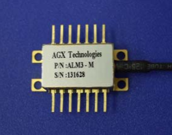
FE50MLxR 650 nm DC-50 MBd 50 m LC POF Transceiver
- Technology
- Fibre optic transceivers
- Partner
- Firecomms
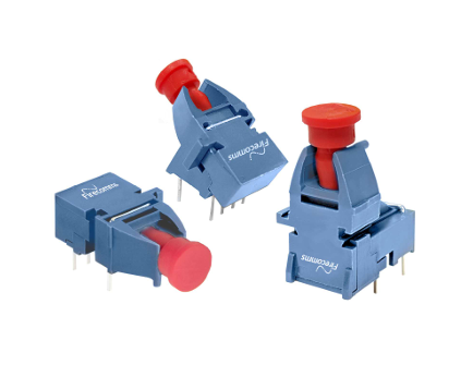
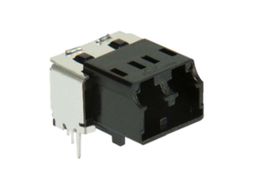
The FE50MLIR/FE50MLNR series is a pair of plastic optical fibre transceiver modules designed for robust, short-range data communications in industrial and automotive systems. Each module incorporates a 650 nm resonant-cavity LED transmitter and a matching photodiode receiver in a single small form-factor housing that mates with standard LC duplex fiber connectors. This design allows engineers to quickly add POF (Plastic Optical Fibre) links to replace or complement copper connections, gaining the benefits of EMI immunity and galvanic isolation.
Supporting data rates from DC up to 50 MBd (approximately 50 Mbps of NRZ data), these transceivers can carry fieldbus and Fast Ethernet-type signals across manufacturing equipment, robotics, or transportation networks. The modules are built for harsh environments, operating reliably from -40 °C to +85 °C and withstanding vibration thanks to the latched LC connector’s secure retention. With compatibility for both 5 V and 3.3 V logic levels and options for inverting or non-inverting signal logic, the FE50MLxR series offers a plug-and-play fibre solution for designers looking to achieve high-noise-immunity data links using inexpensive polymer fibre.
Range features
A high level overview of what this range offers
- Standard LC Duplex Interface – Uses a miniature IEC 61754-20 compliant LC duplex connector for easy, plug-in fiber termination with a secure click-lock mechanism.
- Supports DC to 50 MBd Data Rates – Accommodates a wide range of protocols (up to ~50 Mbps) including industrial Ethernet and serial links, enabling flexible use in control networks.
- Visible 650 nm Red LED Emitter – Utilises a high-reliability RCLED at 650 nm, making the optical link visible for quick troubleshooting while delivering efficient coupling into plastic fiber.
- Integrated Tx/Rx Pair – Combines a transmitter and receiver in one compact module, simplifying system design and providing an instant optical link with matched components.
- Dual Supply Voltage (3.3 V or 5 V) – Operates with either 5 V or 3.3 V power rails, allowing easy integration into both legacy TTL systems and modern low-voltage designs.
- Inverting & Non-Inverting Options – Available in two logic variants (FE50MLIR inverting, FE50MLNR non-inverting) to match the required signal polarity without extra circuitry.
- Signal Detect Output – Incorporates a link detect indicator pin that lets the host system sense the presence of an optical signal, improving reliability and diagnostics.
- 50 m Reach Over POF – Enables data transmission over distances up to 50 metres (typical) using 1 mm step-index POF, adequate for machine interconnects and in-vehicle links (30 m in worst-case conditions).
- Industrial Temperature Range – Designed for -40 °C to +85 °C operation, ensuring stable performance in extreme outdoor, factory floor, or automotive environments.
- High EMI Immunity – Using optical fiber instead of copper eliminates electromagnetic interference issues and provides inherent electrical isolation for sensitive communication lines.
Downloads
for FE50MLxR 650 nm DC-50 MBd 50 m LC POF Transceiver
What’s in this range?
All the variants in the range and a comparison of what they offer
| Parameter | FE50MLIR (Inverting) | FE50MLNR (Non-Inverting) |
|---|---|---|
Wavelength | 650 nm (visible red) | 650 nm (visible red) |
Data rate | DC – 50 MBd | DC – 50 MBd |
Optical fiber type | Step-index POF, 1 mm core (2.2 mm jacket) | Step-index POF, 1 mm core (2.2 mm jacket) |
Typical link distance | 50 m (with standard SI-POF) | 50 m (with standard SI-POF) |
Worst-case distance | 30 m (under maximum attenuation) | 30 m (under maximum attenuation) |
Connector interface | LC duplex (IEC 61754-20 compliant) | LC duplex (IEC 61754-20 compliant) |
Supply voltage | 5 V or 3.3 V (dual-voltage) | 5 V or 3.3 V (dual-voltage) |
Logic polarity | Inverting logic | Non-inverting logic |
Signal detect output | Yes (active on optical signal) | Yes (active on optical signal) |
Operating temperature | -40 °C to +85 °C | -40 °C to +85 °C |
Compliance | RoHS compliant | RoHS compliant |
FAQs
for FE50MLxR 650 nm DC-50 MBd 50 m LC POF Transceiver
The two variants are functionally identical in optical performance and specifications, but they differ in their logic signal polarity. FE50MLIR is the inverting version, meaning its transmitter LED is driven ON by a low input and the receiver outputs an inverted logic level relative to the light input. FE50MLNR is the non-inverting version, where a high input turns the transmitter LED ON and the receiver’s output logic follows the optical signal. This allows designers to choose the module that best fits their required logic conventions without additional signal inversion circuitry.
These modules are designed for step-index polymer optical fiber (SI-POF) with a 1 mm core diameter (usually with a 2.2 mm outer jacket). The front interface is a standard LC duplex connector, adapted for POF. In practice, you will use LC duplex POF plugs (available for plastic fiber) which comply with the IEC 61754-20 standard. Standard glass-fiber LC patch cords are not compatible because of the different fiber core size – you must use POF cables terminated in LC connectors specifically made for 1 mm plastic fiber.
The FE50MLIR/NR modules support data rates up to 50 MBd, which is sufficient for communication protocols around 50 Mbit/s. Traditional 100BASE-FX Fast Ethernet requires 125 MBd, which is higher than this module’s specified rate. However, in many industrial Ethernet or control applications, the transceiver can be used for lower-rate or fast control network links, or potentially for Fast Ethernet over shorter distances with reduced line coding overhead. In general, for a full 100 Mbps Ethernet link, a higher-speed POF transceiver would be needed; the FE50MLxR is more suited for applications in the tens of Mbps range (such as certain fieldbus systems or custom protocols) and for providing robust optical links in noisy environments.
The transceivers are rated for a typical link length of up to 50 metres using standard 1 mm step-index plastic optical fiber under normal operating conditions. This assumes good quality fiber, proper termination, and alignment. In worst-case conditions – such as maximum LED aging, higher temperature, or poor fiber quality – the reliable distance may reduce to around 30 metres. It’s important to note that actual achievable distance can depend on factors like fiber bend radius, connector losses, and any additional link budget margin. For most short-distance industrial applications (machine-to-machine or within a vehicle), 30–50 m of POF coverage is usually sufficient.
The FE50MLIR/NR transceivers come with integrated driver and receiver circuitry that output digital logic-level signals. They are compatible with both 5 V TTL and 3.3 V CMOS logic, which means you can connect the transmitter input and receiver output directly to microcontroller, FPGA, or ASIC I/O pins (ensuring you choose the correct variant for the polarity your system expects). The modules are also stated to be LVDS-compatible, indicating that the signal levels and transition speeds can interface well with low-voltage differential signaling circuits if needed (for example, by using external LVDS transceivers). In practice, you will simply provide a logic data signal to the transmitter pin, and read the digital output from the receiver pin; no complex external conditioning is required. Just be sure to also utilize the Signal Detect (SD) output if you want to know whether a valid optical signal is present at the receiver.
The Signal Detect output is a status indicator pin on the transceiver’s receiver side. It typically goes high (or low, depending on the design) when sufficient optical power is being received – in other words, it tells you that a light signal is present and the link is live. Engineers can use this SD output to implement a Link Loss Alert or carrier-detect feature in their system. For instance, if the fiber is unplugged or broken, the SD pin would change state (signaling loss of light), allowing the host controller to take appropriate action (such as raising an alarm or switching to a backup link). The SD output improves system reliability and diagnostics by providing real-time feedback on the health of the optical connection.
Plastic Optical Fiber (POF) transceivers offer several advantages in industrial and automotive contexts. Firstly, fiber links are immune to electromagnetic interference, so using an optical transceiver ensures robust data communication in electrically noisy environments (for example, next to motors or power lines) where copper might suffer from noise or require heavy shielding. Secondly, POF provides electrical isolation between devices – there’s no conductive path, which enhances safety and eliminates ground loop issues. The FE50MLxR transceiver specifically allows an easy drop-in replacement for copper because of its small LC form factor and logic-level interface. Additionally, POF is lightweight, flexible, and easy to install (it can be cut to length and terminated on site without special tools), and the LC duplex connector offers a familiar, convenient plug interface. Overall, choosing this optical transceiver can result in improved reliability, simpler compliance with EMI/EMC requirements, and potentially lower maintenance in the long run.
Yes – the FE50MLIR/FE50MLNR transceivers are well-suited for automotive and transportation uses, as well as other harsh environments. They are specified over the -40 °C to +85 °C industrial temperature range, which covers the typical automotive grade requirements for inside-vehicle electronics. Plastic optical fiber has already seen use in automotive networks (like MOST Bus and others) for its noise immunity. The LC POF solution provided by these modules adds the benefit of a locking connector for secure connections even under vibration. With their dual-voltage capability, they can interface with both legacy 5 V systems and newer 3.3 V logic in vehicles. These modules could be used for in-vehicle communication links, infotainment data links, or connections between sensors and control units where electrical isolation and EMI robustness are important. It should be noted that for full automotive qualification (AEC-Q), one should verify the transceiver’s compliance, but the fundamental design and spec make them viable for transport and outdoor industrial scenarios.
The transceiver is designed as a small form-factor receptacle that would typically be PCB-mounted. It mates with an LC duplex plug from the outside, so mechanically it has a port for the LC connector and pins that solder onto your printed circuit board. The exact mounting arrangement and PCB footprint will be provided in the module’s datasheet (dimensions and recommended land pattern). Generally, such transceivers are through-hole or board-edge devices that you solder onto the PCB such that the LC connector end is accessible at the panel or edge of the board. You will need to ensure the PCB layout matches the transceiver’s pin configuration (power, ground, Tx data in, Rx data out, SD pin, etc.). It’s also advisable to follow good high-speed design practices: decouple the power pins with capacitors, keep the signal tracks short, and if using differential signaling, route the pair accordingly. By following the guidelines in the data sheet, mounting the FE50MLxR is straightforward and similar to integrating any standard fiber-optic or SFP-type module, just adapted for the LC POF interface.
No external driver or amplifier is required for the optical link – the FE50MLIR/NR modules have an integrated driver IC for the LED transmitter and an integrated preamplifier for the photodiode receiver. This means you can feed data signals directly into the transmitter pin and get logic-level output from the receiver pin without additional analog front-end components. The module is essentially plug-and-play from an electrical perspective. You just need to provide a suitable power supply (5 V or 3.3 V) and bias as specified, and then treat the Tx/Rx pins like any standard serial data interface. The built-in driver ensures the LED can switch at the required speed (up to 50 MBd), and the internal amplifier shapes the received signal into clean digital pulses. This greatly simplifies design compared to discrete LED/photodiode solutions. Just be sure to respect the recommended driving voltage levels and not exceed the absolute maximum ratings. If you are interfacing to longer cables or particularly high-speed edges, minimal line conditioning (like a source termination resistor) might be used on the data input for signal integrity, but typically no special external circuitry is mandated to achieve 50 MBd performance with these transceivers.