CT-0155TSP-MB2L-E 1310 nm FP 2 km 155 Mb/s SFP Transceiver w. DDMI
- Technology
- Optical transceivers
- Partner
- Coretek
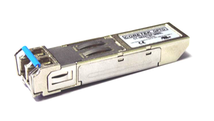
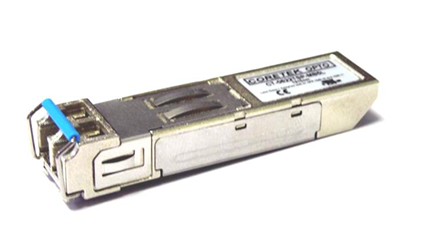
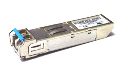
The CT-0155TSP-MB2L-E is a pluggable optical transceiver for serial data communication over multi-mode fibre. Its FP laser operates at a nominal wavelength of 1310 nm, with the optical link specified for distances up to 2 km. Although the nominal application rate is 155 Mb/s, the module accepts NRZ data rates from 50 to 200 Mb/s. Listed applications include Fast Ethernet, FDDI, ATM, SONET OC-3, SDH STM-1 and SONET OC-1 SR-0 links. A duplex LC receptacle and SFP MSA-compatible format support integration with standard SFP host interfaces. Digital diagnostic monitoring is accessible through a two-wire I²C interface compatible with SFF-8472. The -40 to +85°C case temperature range supports consideration for equipment exposed to extended operating temperatures.
Range features
A high level overview of what this range offers
- 1310 nm FP laser: Provides the specified optical interface for multi-mode fibre links up to 2 km.
- 50 to 200 Mb/s NRZ operation: Supports several legacy Ethernet, FDDI and optical transport data rates.
- -19 to -12 dBm optical output: Provides an 11 dB calculated difference between minimum launch power and the -30 dBm receiver sensitivity at 155 Mb/s, before link penalties.
- SFF-8472 DDMI: Enables host access to digital diagnostic information through a two-wire I²C interface.
- Duplex LC SFP format: Supports removable optical connections and integration with SFP MSA-compatible host interfaces.
- 3.1 to 3.5 V operating supply: Matches nominal 3.3 V SFP power architectures.
- -40 to +85°C case temperature range: Supports equipment operating across an extended thermal range.
- Host control and status signals: TX_DISABLE, TX_FAULT and RX_LOS provide transmitter control, fault reporting and optical link-state indication.
- ITU G.957-compliant output eye: Supports the applicable optical waveform requirements.
- RoHS-compliant, lead-free construction: Supports restricted-substance requirements in equipment designs.
- Class 1 laser classification: Defines the laser-safety category for installation and handling.
Downloads
for CT-0155TSP-MB2L-E 1310 nm FP 2 km 155 Mb/s SFP Transceiver w. DDMI
What’s in this range?
All the variants in the range and a comparison of what they offer
Specifications
| Category | Parameter | Specification | Conditions or notes |
|---|---|---|---|
General | Product identifier | CT-0155TSP-MB2L-E | SFP optical transceiver |
General | Fibre type | Multi-mode fibre | Optical output measured using 62.5/125 µm fibre |
General | Optical connector | Duplex LC | SFP MSA-compatible format |
General | Specified link distance | 2 km | Nominal operation at 155 Mb/s |
General | Supported data-rate range | 50 to 200 Mb/s | NRZ |
General | Electrical interface | AC/AC differential interface | TTL signal-detect output |
General | Digital diagnostics | SFF-8472 DDMI | Two-wire I²C serial interface |
General | Standards and applications | IEEE 802.3u 100BASE-FX, FDDI PMD, ATM, SONET OC-3, SDH STM-1 and SONET OC-1 SR-0 | Characterised according to Telcordia GR-468-CORE |
Operating conditions | Case operating temperature | -40 to +85°C | Case temperature |
Operating conditions | Supply voltage | 3.1 to 3.5 V | 3.3 V nominal |
Operating conditions | Data input voltage swing | 400 to 1,600 mV | Differential input |
Absolute maximum ratings | Storage temperature | -40 to +85°C | Storage rating |
Absolute maximum ratings | Supply voltage | 0 to 6 V | Not an operating range |
Absolute maximum ratings | Data input voltage | 0 V to VCC | Absolute maximum rating |
Electrical | Transmitter supply current | 200 mA maximum | ICCT |
Electrical | Receiver supply current | 100 mA maximum | ICCR |
Electrical | TX_DISABLE low input | 0 to 0.8 V | Transmitter enabled |
Electrical | TX_DISABLE high input | 2.0 V to VCC | High or open disables the transmitter |
Electrical | TX_FAULT low output | 0 to 0.8 V | Low logic level |
Electrical | TX_FAULT high output | 2.0 V to VCC | High logic level |
Electrical | Receiver differential output voltage | 0.4 to 1.3 V | VOD |
Electrical | RX_LOS low output | 0 to 0.8 V | Low logic level |
Electrical | RX_LOS high output | 2.0 V to VCC | High logic level |
Electrical | MOD-DEF(1) and MOD-DEF(2) low input | -0.6 V to VCC × 0.3 | Two-wire serial interface |
Electrical | MOD-DEF(1) and MOD-DEF(2) high input | VCC × 0.7 to VCC + 0.5 V | Two-wire serial interface |
Transmitter | Optical output power | -19 to -12 dBm | Average power coupled into 62.5/125 µm multi-mode fibre |
Transmitter | Extinction ratio | 8.2 dB minimum | Minimum optical extinction ratio |
Transmitter | Centre wavelength | 1,263 to 1,360 nm | 1,310 nm typical |
Transmitter | Spectral width | 3 nm maximum | RMS |
Transmitter | Optical rise time | 2.0 ns maximum | 10% to 90% |
Transmitter | Optical fall time | 2.0 ns maximum | 10% to 90% |
Transmitter | Output eye | ITU G.957 compliant | Optical waveform requirement |
Receiver | Maximum input optical power | -3 dBm | Measured with 2^23 – 1 PRBS at BER below 10^-10 |
Receiver | Sensitivity at 51.8 Mb/s | -30 dBm | Measured with 2^23 – 1 PRBS at BER below 10^-10 |
Receiver | Sensitivity at 125 Mb/s | -31 dBm | Measured with 2^23 – 1 PRBS at BER below 10^-10 |
Receiver | Sensitivity at 155 Mb/s | -30 dBm | Measured with 2^23 – 1 PRBS at BER below 10^-10 |
Receiver | Sensitivity at 200 Mb/s | -29 dBm | Measured with 2^23 – 1 PRBS at BER below 10^-10 |
Receiver | Operating wavelength | 1,100 to 1,600 nm | Receiver optical window |
Receiver | Loss-of-signal asserted level | -45 dBm | PA |
Receiver | Loss-of-signal deasserted level | PA + 0.5 dB to -30 dBm | PD |
Receiver | Loss-of-signal hysteresis | 0.5 to 4 dB | PD – PA |
Timing | TX_DISABLE assert time | 10 µs maximum | Maximum control response time |
Timing | TX_DISABLE negate time | 1 ms maximum | Maximum transmitter-enable time |
Timing | Initialisation time | 300 ms maximum | Includes TX_FAULT reset |
Timing | Fault-to-TX_FAULT assertion | 100 µs maximum | Maximum fault-reporting time |
Timing | TX_DISABLE-to-reset time | 10 µs maximum | Maximum reset time |
Timing | RX_LOS assertion time | 100 µs maximum | Off to on |
Timing | RX_LOS deassertion time | 100 µs maximum | On to off |
Materials | Substance compliance | RoHS compliant and lead-free | Restricted-substance construction |
Laser safety | Classification | Class 1 laser product, hazard level 1 | IEC 60825-1 Ed.2 and applicable FDA laser performance standards |
EMC design | Emissions and immunity | Designed for FCC Class B limits and radio-frequency electromagnetic-field immunity | Compliance must be assessed in the complete equipment |
Pin assignment
| Pin | Signal | Function |
|---|---|---|
1 | VeeT | Transmitter ground |
2 | TX Fault | Transmitter fault indication |
3 | TX Disable | Transmitter disable; high or open disables the module |
4 | MOD-DEF(2) | Two-wire serial identification interface |
5 | MOD-DEF(1) | Two-wire serial identification interface |
6 | MOD-DEF(0) | Grounded within the module |
7 | Rate Select | Not connected |
8 | LOS | Loss-of-signal output |
9 | VeeR | Receiver ground |
10 | VeeR | Receiver ground |
11 | VeeR | Receiver ground |
12 | RD- | Inverted received-data output |
13 | RD+ | Received-data output |
14 | VeeR | Receiver ground |
15 | VccR | Receiver power |
16 | VccT | Transmitter power |
17 | VeeT | Transmitter ground |
18 | TD+ | Transmitter-data input |
19 | TD- | Inverted transmitter-data input |
20 | VeeT | Transmitter ground |
FAQs
for CT-0155TSP-MB2L-E 1310 nm FP 2 km 155 Mb/s SFP Transceiver w. DDMI
Yes, the specified reach is 2 km over multi-mode fibre, provided the installed link remains within the available optical and dispersion limits. At 155 Mb/s, minimum launch power is -19 dBm and receiver sensitivity is -30 dBm, producing an 11 dB calculated power difference before connector, splice, ageing, temperature and implementation penalties are included. Maximum launch power is -12 dBm, while the receiver input limit is -3 dBm, so the stated figures do not indicate an overload problem on a direct link. The final design should still include an end-to-end loss calculation based on the selected fibre and connector count. Suitable engineering margin should be retained rather than using the entire calculated budget.
The module is intended primarily for 155 Mb/s operation but accepts NRZ data rates from 50 to 200 Mb/s. Listed applications include Fast Ethernet, FDDI, ATM, SONET OC-3, SDH STM-1 and SONET OC-1 SR-0, with receiver sensitivity figures provided at 51.8, 125, 155 and 200 Mb/s. This range allows the same optical module to be considered for several legacy transport and industrial communication links. Optical compatibility does not implement protocol framing, encoding, clocking or management functions within the host. The electrical serial interface and protocol layer must therefore both be checked when selecting the module.
The CT-0155TSP-MB2L-E provides an SFF-8472-compatible digital diagnostic interface through a two-wire I²C connection. MOD-DEF(1) and MOD-DEF(2) carry the serial interface, while MOD-DEF(0) is grounded within the module. Individual monitored parameters, measurement accuracy, alarm thresholds and calibration details are not specified. Host software should therefore avoid assuming particular diagnostic fields or tolerances until the module memory map has been verified during integration. Prototype testing should include reading the identification and diagnostic pages under normal, low-temperature and high-temperature conditions.
The module requires a regulated 3.3 V supply operating between 3.1 and 3.5 V. Maximum transmitter and receiver currents are 200 mA and 100 mA respectively, so the host should allow for an aggregate module current of up to 300 mA before adding design margin. At the maximum operating voltage, this corresponds to approximately 1.05 W if both stated current limits occur together. The differential data input swing is 400 to 1,600 mV, while the receiver differential output is 0.4 to 1.3 V. Separate VccT and VccR pins should be accommodated with appropriate local filtering, decoupling and hot-plug considerations.
The host should allow up to 300 ms for module initialisation, including the reset of TX_FAULT. TX_DISABLE can assert within 10 µs and may require up to 1 ms to negate, while a transmitter fault can take up to 100 µs to appear at TX_FAULT. The reset process initiated through TX_DISABLE has a maximum specified time of 10 µs. Receiver loss-of-signal assertion and deassertion are each specified at up to 100 µs. These limits should be reflected in the port state machine so that hot insertion, power-up and transmitter enabling do not produce premature fault declarations.
No, RX_LOS should be treated as a link-state indication rather than a substitute for bit-error-rate testing. The asserted level is listed at -45 dBm, while the deasserted level is bounded from PA + 0.5 dB to -30 dBm, with hysteresis between 0.5 and 4 dB. Receiver sensitivity at 155 Mb/s is -30 dBm when measured using a 2^23 – 1 PRBS at a BER below 10^-10. The LOS circuit and the data receiver therefore perform related but different functions. A port can deassert LOS without providing the system-level operating margin required for stable traffic, so received power and error performance should also be validated.
The specified case operating range is -40 to +85°C, and the storage range is also -40 to +85°C. This allows the module to be considered for outdoor, transport or industrial equipment when the SFP cage temperature remains within those limits. The construction is identified as RoHS compliant and lead-free, while the optical transmitter is classified as a Class 1 laser product. The EMC design targets FCC Class B limits and immunity to radio-frequency electromagnetic fields, but compliance still needs to be assessed in the finished equipment. Shock, vibration, humidity and thermal-cycling ratings are not specified, so applications with additional environmental demands require separate qualification.
The optical interface uses a duplex LC receptacle and is intended for multi-mode fibre. Transmitter output power is measured with 62.5/125 µm multi-mode fibre, making that the explicitly referenced fibre construction for the optical power figures. The transmitter centre wavelength ranges from 1,263 to 1,360 nm, with 1,310 nm typical, while the receiver operating window is 1,100 to 1,600 nm. The broad receiver wavelength range does not make the module interchangeable with every optical system, because launch power, receiver sensitivity, overload, data rate and fibre bandwidth must also match. Replacement or new-port designs should additionally verify connector polarity and compatibility with the intended SFP host cage.