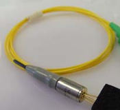
RLMR3 1310 nm 4 mW 3 GHz Coaxial Analogue DFB Laser (Return Path)
- Technology
- Analogue - RF over fibre - components
- Partner
- AGx Technologies
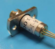
The RDLMR3-A-1-4-FU is a 1310 nm multi-quantum-well DFB laser module configured for an optical output of at least 4 mW. It combines an analogue laser, a single internal optical isolator and an FC/UPC receptacle within a compact, hermetically sealed coaxial package. Its 3 GHz bandwidth is intended for CATV return-path links and RF-over-fibre transmission. The device supports uncooled operation across a temperature range of -20 to +85 °C. An internal monitor photodiode allows a compatible laser driver to monitor and regulate optical output. Optical characteristics include at least 30 dB side-mode suppression and 30 dB isolation. The Type A electrical pin configuration and specified maximum ratings must be considered when selecting the driver circuit and developing the PCB layout.
Range features
A high level overview of what this range offers
- 1310 nm MQW DFB laser: Supports analogue optical transmission for return-path and RF-over-fibre links.
- ≥4 mW output-power class: Provides a defined minimum optical output for link-budget calculations.
- 3 GHz bandwidth: Accommodates broadband RF modulation within the stated bandwidth.
- RIN of no more than -145 dB/Hz: Supports low-noise analogue links from 5 to 300 MHz under the stated conditions.
- IMD2 ≤ -50 dBc and IMD3 ≤ -57 dBc: Provides reference values for analogue linearity planning.
- Internal optical isolator: Can reduce the effects of optical feedback from external reflections.
- Internal monitor photodiode: Enables optical-power monitoring and automatic power-control circuits.
- -20 to +85 °C operation: Supports uncooled use across a broad equipment temperature range.
- Hermetically sealed coaxial package: Protects the laser element while providing a compact receptacle format.
- FC/UPC optical interface: Provides a defined connector option for integration with compatible fibre assemblies.
- RoHS compliance: Supports designs with restricted-substance requirements.
Downloads
for RLMR3 1310 nm 4 mW 3 GHz Coaxial Analogue DFB Laser (Return Path)
What’s in this range?
All the variants in the range and a comparison of what they offer
Electro-optical specifications
| Parameter | Symbol | Conditions | Minimum | Maximum | Unit |
|---|---|---|---|---|---|
Operating temperature | T_OP | I_F = I_OP | -20 | 85 | °C |
Threshold current at 25 °C | I_TH | T = 25 °C | — | 15 | mA |
Threshold current at 85 °C | I_TH | T = 85 °C | — | 40 | mA |
Operating current | I_OP | T = T_OP | — | 90 | mA |
Operating voltage | V_OP | — | — | 2.1 | V |
Operating output power | P_O | Model option y = 4 | ≥4 | — | mW |
Monitor photodiode responsivity | r_MPD | — | 10 | 2,000 | μA |
Monitor photodiode dark current | I_D | I_OP = 0 mA | — | 0.2 | μA |
Operating wavelength | λ_OP | I_F = I_OP, T = T_OP | 1,290 | 1,330 | nm |
Side-mode suppression ratio | SMSR | I_F = I_OP | 30 | — | dB |
Optical isolation | ISO | Single isolator | 30 | — | dB |
Tracking error | E_R | — | -1.5 | +1.5 | dB |
Bandwidth | — | — | 3 | — | GHz |
Second-order intermodulation | IMD2 | Rated power, 25 °C, 10% OMI, two-tone test at 13 and 19 MHz, received power -4 dBm | — | -50 | dBc |
Third-order intermodulation | IMD3 | Rated power, 25 °C, 10% OMI, two-tone test at 13 and 19 MHz, received power -4 dBm | — | -57 | dBc |
Relative intensity noise | RIN | 5 to 300 MHz | — | -145 | dB/Hz |
Ordering scheme
| Segment | Function | Code | Meaning |
|---|---|---|---|
Prefix | Product series | RDLMR3 | 1310 nm DFB receptacle laser |
X | Pinout | A | Type A |
N | Number of isolators | 1 | Single isolator |
y | Output power | 1 | ≥1 mW |
y | Output power | 2 | ≥2 mW |
y | Output power | 3 | ≥3 mW |
y | Output power | 4 | ≥4 mW |
z | Optical connector | FU | FC/UPC |
Configured part number: RDLMR3-A-1-4-FU
Maximum ratings
| Parameter | Conditions | Minimum | Maximum | Unit |
|---|---|---|---|---|
Storage temperature | Continuous | -40 | 85 | °C |
Monitor photodiode reverse voltage | 60 seconds | — | 15 | V |
Monitor photodiode reverse voltage | Continuous | — | 10 | V |
Forward DC laser current | Continuous | — | 100 | mA |
Reverse DC laser voltage | Continuous | — | 1 | V |
Type A pin configuration
| Pin | Connection |
|---|---|
1 | PD+ |
2/GND | LD+ |
3 | LD- |
4 | PD- |
FAQs
for RLMR3 1310 nm 4 mW 3 GHz Coaxial Analogue DFB Laser (Return Path)
The module is specified for CATV return-path and RF-over-fibre applications, combining 1310 nm emission with a 3 GHz bandwidth. Its analogue performance figures include IMD2 of no more than -50 dBc and IMD3 of no more than -57 dBc under rated-power, 25 °C, 10% optical modulation index and two-tone test conditions. Relative intensity noise is specified at no more than -145 dB/Hz from 5 to 300 MHz. These figures provide a basis for initial noise and linearity calculations, although the distortion test conditions do not establish identical performance across the entire 3 GHz bandwidth. The complete transmitter, fibre path and receiver should therefore be validated against the intended channel plan and optical loss budget.
The y = 4 option defines an optical output-power class of at least 4 mW rather than an exact 4 mW operating value. In the complete RDLMR3-A-1-4-FU code, A selects the Type A pinout, 1 specifies a single optical isolator, 4 identifies the ≥4 mW class and FU specifies the FC/UPC interface. The electro-optical specifications link operating power to this model code without stating an upper output limit. Link budgets should therefore use 4 mW as the specified minimum rather than assuming a fixed launch power. Applications with a strict maximum transmitter power should confirm that requirement separately before final selection.
The laser is intended for uncooled operation and has a specified operating temperature range of -20 to +85 °C. Threshold current can reach 15 mA at 25 °C and 40 mA at 85 °C, while operating current can reach 90 mA across the stated temperature range. The laser driver must also accommodate an operating voltage of up to 2.1 V. Its internal monitor photodiode, with a stated response range of 10 to 2,000 μA, can be incorporated into an automatic power-control loop. In practice, the bias circuit should have sufficient adjustment range to maintain the required optical output as threshold current and device behaviour change with temperature.
The module contains a single internal optical isolator with at least 30 dB isolation, which can reduce optical feedback reaching the DFB laser. It also provides a minimum side-mode suppression ratio of 30 dB for the stated operating condition. These characteristics support stable analogue operation, but they do not eliminate the need to manage reflections elsewhere in the fibre path. The FC/UPC receptacle should be connected to a clean, compatible FC/UPC fibre interface, and an FC/APC connector should not be directly mated to it. Reflective components, poor connector end faces and multiple open interfaces should be assessed during system-level testing because an allowable reflected-power limit is not defined.
The maximum ratings are stress limits and should not be treated as normal operating targets. Forward DC laser current is limited to 100 mA continuously, compared with a maximum stated operating current of 90 mA, while reverse DC voltage across the laser must not exceed 1 V. The monitor photodiode reverse-voltage limit is 10 V continuously or 15 V for no more than 60 seconds. Its dark current is specified at up to 0.2 μA when the laser operating current is zero. The driver design should include current limiting, reverse-voltage protection and transient control, with operating margins that prevent start-up or fault conditions from approaching these limits.
The Type A arrangement assigns pin 1 to PD+, pin 2/GND to LD+, pin 3 to LD- and pin 4 to PD-. The pin 2/GND notation means that the grounding and laser-driver topology must be reviewed carefully rather than applying a generic laser-diode footprint. Monitor photodiode polarity must also be observed if its current is used in an automatic power-control loop. The stated monitor response range of 10 to 2,000 μA means that the feedback amplifier should provide a suitable input range and calibration adjustment. PCB documentation should clearly identify both the electrical pin orientation and the optical receptacle orientation before the assembly is released for production.
Mechanical interchangeability should not be assumed solely from the coaxial package description. Compatibility depends on the mounting flange, fixing-hole positions, receptacle projection, pin clearance, panel arrangement and available space around the fibre connector. A mechanical outline is supplied for checking these details, but its dimensions are presented only within the drawing and are not reproduced as tabulated values here. The optical interface is FC/UPC, while the electrical connection uses the four-position Type A configuration. Before finalising the enclosure or PCB, the complete outline should be checked against mounting hardware, panel thickness, fibre bend requirements and the selected laser-driver layout.