Lock-In Amplifiers DC-200 MHz
- Technology
- Lock-in Amplifiers
- Partner
- Stanford Research Systems (SRS)
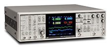
This range comprises six bench lock-in amplifiers using single- or dual-phase analogue and DSP architectures. Collectively, the models cover specified reference frequencies from 1 mHz to 200 MHz, although each instrument operates only within its stated band. The lower- and mid-frequency models support small voltage and current measurements, while the SR844 provides 50 Ω and 1 MΩ RF inputs for operation from 25 kHz to 200 MHz. The SR2124 is designed for sensitive experiments in which continuous digital clock activity may introduce interference, including low-temperature measurements.
The SR860 and SR865A add touchscreen displays, FFT views, capture memory and modern remote interfaces for automated or data-intensive systems. Model-dependent reference functions include internal, external, harmonic, dual-frequency, chopper and VCO modes. Typical applications include chopped optical measurements, detector-current measurements, frequency-selective AC testing, transport measurements and other synchronous-detection experiments. Instrument selection should consider reference frequency, source impedance, required dynamic reserve, time constant, harmonic mode, data handling and control interface.
Range features
A high level overview of what this range offers
- Six analogue and DSP models – Choose from low-frequency single-phase instruments through to 200 MHz dual-phase RF detection.
- Combined 1 mHz to 200 MHz frequency coverage – Select an amplifier around the experiment’s actual modulation or reference frequency.
- Voltage and current inputs on five models – Connect voltage-output sensors and a wide range of current-output detectors.
- Dynamic reserve up to 120 dB typical – Recover weak signals in the presence of substantially larger interfering signals.
- Time constants from 1 µs to 30 ks across the range – Balance settling speed against equivalent noise bandwidth.
- Internal, external and harmonic reference modes – Support fundamental, harmonic, double-modulation and chopped measurements, depending on the model.
- Touchscreen, FFT and analysis functions on selected models – Simplify setup, noise diagnosis and acquired-data review.
- GPIB, RS-232, USB, Ethernet or fibre-optic control – Integrate with legacy, isolated and networked automated systems.
- Clock-stopped SR2124 analogue architecture – Perform sensitive experiments where continuous digital clock activity is undesirable.
- Selectable high-pass, low-pass, band-pass, notch and synchronous filters – Apply model-dependent rejection of unwanted spectral components.
Downloads
for Lock-In Amplifiers DC-200 MHz
What’s in this range?
All the variants in the range and a comparison of what they offer
Range specifications
| Parameter | Range details |
|---|---|
Unique models | SR865A, SR860, SR2124, SR844, SR850 and SR510 |
Architectures | Analogue single-phase, analogue dual-phase and DSP dual-phase |
Combined reference-frequency coverage | 1 mHz to 200 MHz across the complete range |
Current inputs | Available on SR865A, SR860, SR2124, SR850 and SR510 |
Minimum stated voltage output scale | 1 nV on SR865A and SR860 |
Highest specified dynamic reserve | 120 dB typical on SR865A and SR860 |
Selectable time constants | 1 µs shortest standard selection and 30 ks longest selection, depending on model |
Remote interfaces | Model-dependent GPIB, RS-232, USB, Ethernet and fibre-optic connectivity |
AC supply | 100, 120, 220 or 240 VAC; 50/60 Hz |
Power consumption | 35 W to 70 W, depending on model |
Overall dimensions | 17 in wide; 3.5 in to 6.25 in high; 17 in to 19.5 in deep |
Weight range | 12 lb to 40 lb |
Variant comparison
| Specification | SR865A | SR860 | SR2124 | SR844 | SR850 | SR510 |
|---|---|---|---|---|---|---|
Architecture | DSP, dual phase | DSP, dual phase | Analogue, dual phase | DSP RF, dual phase | DSP, dual phase | Analogue, single phase |
Frequency range | 1 mHz to 4 MHz | 1 mHz to 500 kHz | 0.2 Hz to 200 kHz | 25 kHz to 200 MHz | 1 mHz to 102.4 kHz | 0.5 Hz to 100 kHz |
Voltage sensitivity or output scale | 1 nV to 1 V | 1 nV to 1 V | 100 nV to 500 mV | 100 nV to 1 V below 1 MHz; 1 µV to 1 V below 50 MHz; 10 µV to 1 V below 200 MHz | 2 nV to 1 V | 100 nV to 500 mV |
Current input | 1 fA to 1 µA output scale; 10 nA or 1 µA peak input range | 1 fA to 1 µA output scale; 10 nA or 1 µA peak input range | 10⁶ or 10⁸ V/A | Not provided | 10⁶ or 10⁸ V/A | 100 fA to 0.5 µA full scale; 10⁶ V/A |
Voltage input impedance | 10 MΩ + 25 pF; AC or DC coupled | 10 MΩ + 25 pF; AC or DC coupled | 10 MΩ + 35 pF; AC or DC coupled | 50 Ω or 1 MΩ + 30 pF | 10 MΩ + 25 pF; AC or DC coupled | 100 MΩ + 25 pF; AC coupled |
Typical voltage noise | 2.5 nV/√Hz at 1 kHz | 2.5 nV/√Hz at 1 kHz | 2.5 nV/√Hz at 1 kHz | 2 nV/√Hz with 50 Ω input; 5 nV/√Hz with 1 MΩ input | 6 nV/√Hz at 1 kHz | 7 nV/√Hz at 1 kHz |
Dynamic reserve | 120 dB typical | 120 dB typical | Up to 60 dB without band-pass filtering; up to 100 dB with band-pass filtering | Up to 80 dB | Greater than 100 dB | Up to 60 dB without tracking band-pass filtering; up to 80 dB with the filter |
Time constants and slopes | 1 µs to 30 ks; 6, 12, 18 or 24 dB/oct | 1 µs to 30 ks; 6, 12, 18 or 24 dB/oct | 1 ms to 300 s; 6 or 12 dB/oct; minimum position typically 500 µs | 100 µs to 30 ks; 6, 12, 18 or 24 dB/oct; filter-bypass mode | 10 µs to 30 ks; 6, 12, 18 or 24 dB/oct | 1 ms to 100 s pre-filter; 0.1 s, 1 s or no post-filter; 6 or 12 dB/oct |
Reference and harmonic modes | Internal, external, dual-frequency and chopper modes; N × reference with N less than 99 | Internal, external, dual-frequency and chopper modes; N × reference with N less than 99 | Internal, external and rear VCO; F, 2F and 3F with external reference | Internal or external; 2F detection | Internal or external; harmonic detection to the frequency limit | External reference; internal oscillator optional; F and 2F detection |
Data and analysis | Four-channel touchscreen, trend and FFT views; 1 Mpoint capture; streaming to 1.25 MHz | Four-channel touchscreen, trend and FFT views; 1 Mpoint capture; streaming to 1.25 MHz | X/Y analogue outputs, AC-voltmeter mode and remote readback | Two 16,000-point buffers; recording to 512 samples/s | 65,536-point memory; smoothing, curve fitting and statistics | Four ADC inputs, two DAC outputs and remote readback |
Remote interfaces | GPIB, RS-232, USB and Ethernet | GPIB, RS-232, USB and Ethernet | RS-232; fibre-optic connection to SX199 for GPIB, RS-232 and Ethernet | GPIB and RS-232 | GPIB, RS-232 and Centronics | RS-232; GPIB optional |
Dimensions, W × H × D | 17 in × 5.25 in × 17 in | 17 in × 5.25 in × 17 in | 17 in × 5.25 in × 19.5 in | 17 in × 5.25 in × 19.5 in | 17 in × 6.25 in × 19.5 in | 17 in × 3.5 in × 17 in |
Weight | 22 lb | 22 lb | 23 lb | 23 lb | 40 lb | 12 lb |
FAQs
for Lock-In Amplifiers DC-200 MHz
No. The range collectively spans 1 mHz to 200 MHz, but no single model covers that entire interval, and lock-in detection is based on an AC signal referenced to a known modulation frequency. The SR865A reaches 4 MHz from 1 mHz, the SR860 reaches 500 kHz, and the SR844 covers the RF band from 25 kHz to 200 MHz; the remaining models occupy lower and mid-frequency ranges. The demodulated result may be a DC output, but that does not make the input a true DC measurement. Use the actual reference-frequency limits in the variant comparison when selecting an instrument.
The primary selection difference is the upper frequency limit: 4 MHz for the SR865A and 500 kHz for the SR860. Both models start at 1 mHz, provide 1 nV to 1 V voltage output scales, include current-input scales down to 1 fA and specify 2.5 nV/√Hz voltage noise at 1 kHz. They also share 120 dB typical dynamic reserve, 1 µs to 30 ks time constants, FFT displays, 1 Mpoint capture and data streaming at rates up to 1.25 MHz. Choose the SR865A when the reference, detected harmonic or anticipated future work may exceed 500 kHz. For measurements remaining below that limit, the SR860 provides a closely aligned measurement, analysis and automation workflow.
Choose the SR844 when the signal or reference frequency exceeds the 4 MHz ceiling of the SR865A, or when a 50 Ω RF signal path is required. Its 25 kHz to 200 MHz band can be used with either a 50 Ω input or a 1 MΩ + 30 pF input, allowing selection between RF matching and higher input impedance. Minimum full-scale sensitivity varies with frequency, from 100 nV below 1 MHz to 10 µV near the 200 MHz limit. Dynamic reserve is available up to 80 dB, while filter bypass provides X and Y update rates of 10 to 20 µs. The SR844 has no built-in current input, so current-output detectors may require a suitable external transimpedance or RF preamplifier.
The SR2124 is intended for measurements in which continuous digital clock activity could couple interference into a sensitive experiment. Its clock-stopping architecture disables digital clock operation once a setting change is complete, and a front-panel lockout can prevent accidental reactivation during a measurement. The instrument covers 0.2 Hz to 200 kHz, provides dual-phase detection, 2.5 nV/√Hz voltage noise and selectable 10⁶ or 10⁸ V/A current-input gain. Its tuneable band-pass filter can raise the maximum achievable dynamic reserve to 100 dB, while F, 2F and 3F detection supports harmonic experiments. Remote commands temporarily reactivate the controller, so their timing should be considered in particularly noise-sensitive installations.
The input should be matched to whether the detector behaves primarily as a voltage source, current source or impedance-matched RF source. High-impedance voltage sources can use the 10 MΩ inputs of the SR865A, SR860, SR2124 and SR850, or the 100 MΩ AC-coupled input of the SR510; however, cable and source capacitance may then restrict bandwidth. Current-output detectors can connect to the built-in current inputs on all models except the SR844, with the available gain, input range and noise depending on the selected instrument. The SR844 provides a 50 Ω input for matched RF systems and a 1 MΩ input for higher-impedance sources. Selection should therefore consider source impedance, capacitance, required bandwidth and input noise rather than sensitivity alone.
Dynamic reserve determines how much larger an interfering signal can be than the selected full-scale signal before measurement accuracy is affected, while the output filter controls noise bandwidth and response time. The SR865A and SR860 specify 120 dB typical reserve, the SR850 exceeds 100 dB, and the SR2124 can reach 100 dB when its band-pass filter is engaged. Longer time constants reduce equivalent noise bandwidth but slow the response to signal changes, frequency sweeps or feedback-loop corrections. The SR865A and SR860 provide time constants from 1 µs to 30 ks with RC, Gaussian and phase-linear filter choices, while the SR844 offers a filter-bypass mode for faster updates. In practice, use the smallest input range that avoids overload, then choose the time constant and slope around the required settling time and signal bandwidth.
The reference system must match the experiment’s modulation arrangement as well as its frequency. The SR865A and SR860 support internal, external, dual-frequency and chopper modes, together with harmonic detection where the multiplier N is less than 99 and the detected frequency remains within the instrument limit. The SR2124 supports internal, external and rear-panel VCO operation with F, 2F and 3F detection, while the SR850 supports higher-order harmonic detection up to its 102.4 kHz ceiling. For automation, the SR865A and SR860 provide GPIB, RS-232, USB and Ethernet, whereas the other models use combinations of GPIB, RS-232, Centronics or fibre-optic control. Choose the detection mode and interface together, particularly where data streaming, legacy software or digital-noise isolation is important.
A detector cable should be discharged and connected to the amplifier before the detector or its high-voltage supply is switched on. An unterminated photomultiplier cable can accumulate a charge large enough to damage a sensitive front-end amplifier, while the SR865A and SR860 specify maximum inputs of 1 V peak or 1 µA peak. Select a voltage or current input according to the detector model, and use a suitable preamplifier when additional isolation, gain or bandwidth control is required. A 50 Ω termination can support high-frequency transmission but may add more current noise than a high-impedance or transimpedance arrangement. Detector bias isolation, cable capacitance, grounding and the amplifier damage threshold should therefore be reviewed before installation.