RF Multiplexers
- Technology
- RF Filters
- Partner
- Sangshin
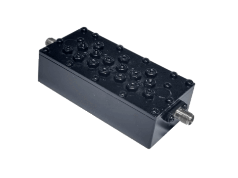
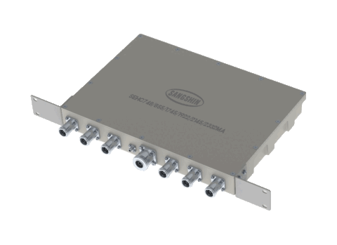
This RF multiplexer range is designed to separate or combine multiple frequency paths within mobile and wireless communication equipment. It includes cavity models for selected multi-port configurations and ceramic monoblock models where a different mechanical format is required. The available frequency plans cover sub-GHz, cellular, PCS, LTE and selected 5 GHz wireless bands. Engineers can compare each configuration by its number of paths, passband frequencies, insertion loss, return loss, ripple, attenuation and enclosure dimensions. The range includes four-, five-, six-, seven- and eight-path options for systems requiring several operating bands to share part of the RF signal chain. Potential applications include mobile communications, TRS, GPS, WLAN, DAB, DMB, WiMAX, RFID and Wi-Fi equipment, subject to compatibility with the specified passbands. Final selection should also consider system-level requirements that are not included in the range data, such as power handling, impedance, connectors and operating temperature.

Designed for mobile and wireless communication equipment, the CAMPX/SEMPX range separates or combines multiple RF paths in compact cavity and ceramic monoblock formats. The portfolio spans selected sub-GHz, cellular, PCS, LTE and 5 GHz wireless bands, with each model defined by its own passbands, insertion loss, return loss, ripple, attenuation and dimensions.
This makes the range suitable for engineers comparing multiband RF filter options for shared signal paths, while keeping in mind that final component selection also requires confirmation of system-level parameters such as power handling, impedance, connectors and operating temperature.
Range features
A high level overview of what this range offers
- Four to eight frequency paths – Provides configurations for combining or separating several operating bands.
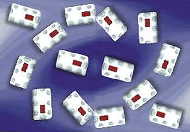
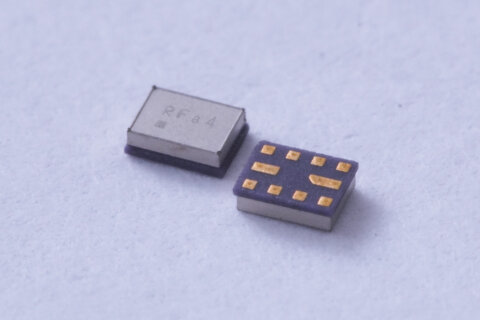
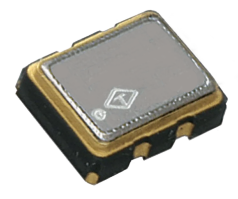
- Cavity and ceramic monoblock technologies – Allows selection according to the required frequency plan, electrical characteristics and mechanical envelope.
- Selected passbands from 300 to 5925 MHz – Covers a mixture of sub-GHz, cellular and 5 GHz wireless frequencies.
- Maximum insertion-loss values from 1.3 to 7.2 dB – Supports path-specific RF link-budget calculations.
- Minimum return-loss values from 11 to 18 dB – Provides defined matching criteria for the listed configurations.
- Minimum rejection values from 30 to 70 dB – Enables assessment of isolation from specified neighbouring frequency ranges.
- Model-specific ripple data – Helps engineers evaluate passband amplitude variation.
- Mechanical dimensions for every listed part – Supports early-stage PCB, enclosure and equipment layout checks.
What’s in this range?
All the variants in the range and a comparison of what they offer
| Part No. | Classification | Normalised Technology | Band | Frequency Paths | Start Freq. [MHz] | Center Freq. [MHz] | Stop Freq. [MHz] | Insertion Loss [dB/max.] | Return Loss [dB/min.] | Ripple [dB/max.] | Attenuation [dB/min.] | Dimensions (L × W × H) [mm] |
|---|---|---|---|---|---|---|---|---|---|---|---|---|
CAMPX30MR836/881/1882/1962NSA | Cavity | Cavity | 4 | 1850 | 1882 | 1915 | 1.5 | 17 | 1 | 70 @ 1930 ~ 1995 | 197 × 111 × 58 | |
CAMPX46MR300/1800/2100/2600NA | Cavity | Cavity | 3 | 8 | PORT 1 380 | PORT 1 382.5 | PORT 1 385 | 4 | 12 | 45 @ 390 ~ 395 | 162 × 120 × 66 | |
SEMPX1000/1955/2525/3425SBPF | MONO | Ceramic Monoblock | 4 | 3050 | 3425 | 3800 | 2.5 | 11 | 1 | 30 @ 300 ~ 2700 | 55 × 40 × 9.5 | |
SEMPX1737-1882-1975-2155-2310-2355-2593CPA | Mono | Ceramic Monoblock | 41 | 7 | 2496 | 2593 | 2690 | 4.8 | 15 | 1.5 | 50 @ 1690 ~ 1780 50 @ 1850 ~ 1915 50 @ 1930 ~ 2020 50 @ 2110 ~ 2200 50 @ 2305 ~ 2315 2305 ~ 2315 2350 ~ 2360 2350 ~ 2360 2350 ~ 2360 2350 ~ 2360 2350 ~ 2360 | 36 × 200 × 12.5 |
SEMPX1795/2045/2350/2595HC | Mono | Ceramic Monoblock | 40 | 4 | 2300 | 2350 | 2400 | 3 | 15 | 1.5 | 30 @ 1710 ~ 1870 30 @ 1920 ~ 2170 30 @ 2500 ~ 2690 | 104 × 52 × 50.25 |
SEMPX1937/2125/2510/2630SB | Mono | Ceramic Monoblock | 4 | 1935 | 1937.5 | 1940 | 3.5 | 18 | 0.7 | 40 @ 2125 ~ 2130 40 @ 2500 ~ 2520 40 @ 2620 ~ 2640 | 17.5 × 40 × 5.4 | |
SEMPX1962/2145/2355/2596/5537SA | Mono | Ceramic Monoblock | 5 | 1930 | 1962.5 | 1995 | 3 | 15 | 1.5 | 30 @ 2110 ~ 2180 30 @ 2345 ~ 2360 30 @ 2496 ~ 2690 30 @ 5150 ~ 5925 | 36 × 79 × 7.5 | |
SEMPX634-689-748-787-833-878CA | Mono | Ceramic Monoblock | 5 | 6 | 862 | 878 | 894 | 5 | 15 | 2.5 | 50 @ 617 ~ 652 40 @ 663 ~ 716 50 @ 728 ~ 768 40 @ 776 ~ 798 45 @ 817 ~ 849 894 894 894 894 | 36 × 200 × 12.5 |
SEMPX707/742/781/836/881SB | Mono | Ceramic Monoblock | 5 | 5 | 869 | 881.5 | 894 | 6 | 15 | 1.5 | 50 @ 698 ~ 716 50 @ 728 ~ 757 50 @ 776 ~ 787 60 @ 824 ~ 849 | 42 × 165 × 13.9 |
SEMPX836/881/1747/1842/1950/2140SC | Mono | Ceramic Monoblock | 1 | 6 | 2110.5 | 2140 | 2169.5 | 4 | 18 | 1 | 60 @ 824 ~ 848 60 @ 869 ~ 893.5 60 @ 1710.5 ~ 1784.5 60 @ 1805.5 ~ 1879.5 50 @ 1920.5 ~ 1979.5 51 @ 2110.5 ~ 2169.5 60 @ 2110.5 ~ 2169.5 60 @ 2110.5 ~ 2169.5 1979.5 60 @ 2110.5 ~ 2169.5 1979.5 60 @ 2110.5 ~ 2169.5 | 46 × 120 × 10 |
SEMPX837/882/1950/2140SA | Mono | Ceramic Monoblock | 1 | 4 | 2130 | 2140 | 2150 | 2.7 | 18 | 0.5 | 50 @ 830 ~ 845 50 @ 875 ~ 890 55 @ 1940 ~ 1960 | 43 × 55 × 10 |
FAQs
for RF Multiplexers
The number of paths identifies how many separate passbands are handled by the multiplexer. The listed range includes models with four, five, six, seven or eight paths.
No. These figures represent the lowest start frequency and highest stop frequency across the complete range. Each part number supports only the specific passbands shown in the specifications table.
Selection should be based on the required frequency plan, insertion loss, return loss, rejection, ripple and available installation space. CAMPX models use cavity construction, while the listed SEMPX models use ceramic monoblock technology.
The CAMPX46MR300/1800/2100/2600NA provides eight paths. Its frequency plan is divided between four Port 1 passbands and four Port 2 passbands.
The SEMPX1937/2125/2510/2630SB measures 17.5 × 40 × 5.4 mm, making it the smallest listed envelope within this range.
The stated minimum attenuation levels range from 30 to 70 dB, depending on the model, signal path and rejection frequency. These values should be checked against the interfering bands present in the intended RF system.
Power handling, nominal impedance and connector details are not included in the range specifications. These parameters require confirmation before a component is incorporated into the final RF design.
Several configurations include frequencies used by cellular and LTE systems, while selected models extend into sub-6 GHz ranges. Suitability depends on whether the individual passbands, bandwidths and rejection regions match the required network band plan.
Multiple figures indicate that electrical performance can differ between paths or groups of paths. Engineers should retain the listed frequency order when matching these values to the relevant passbands.
Customisation capability is not defined within the range data. Any requirement for alternative centre frequencies, bandwidths, connectors or mechanical dimensions should therefore be evaluated separately.