HLVA Logarithmic Voltage Amplifier
- Technology
- Amplifiers
- Partner
- FEMTO Messtechnik
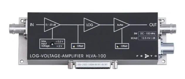
The HLVA-100 logarithmic voltage amplifier is designed for low-level signals whose amplitude can vary over several decades. Its DC-coupled signal path covers DC to 100 MHz and provides logarithmic scaling of 12.5 mV/dB, equivalent to 250 mV per decade into a 50 Ω load. Two switchable input spans cover ±20 µV to ±200 mV and ±200 µV to ±2 V. The amplifier offers a typical 60 dB range for quantitative amplitude measurement and up to 80 dB for signal detection.
A 5 ns rise and fall time supports fast pulse and transient measurements, while the equivalent input voltage noise is 2 nV/√Hz. BNC input and output connections provide compatibility with standard 50 Ω measurement systems. Local adjustment, opto-isolated digital control and sample-and-hold baseline correction support integration into manual and automated test equipment. Typical applications include LiDAR, signal compression, time-resolved pulse measurement, mass spectrometry and particle detection.
Range features
A high level overview of what this range offers
- DC to 100 MHz, DC-coupled signal path: Covers static voltage levels and fast transient content.
- 60 dB typical and 80 dB maximum dynamic range: Compresses wide input-amplitude variation into a manageable output span.
- Two switchable input ranges: Selects either ±20 µV to ±200 mV or ±200 µV to ±2 V to suit the signal level.
- 12.5 mV/dB logarithmic scaling: Provides a defined output change equivalent to 250 mV per decade into 50 Ω.
- 5 ns rise and fall time: Supports time-resolved pulse and transient measurements.
- ±1 dB pulse linearity: Enables quantitative amplitude measurements for pulses at least 20 ns wide.
- 2 nV/√Hz equivalent input noise: Limits amplifier-added noise in low-level measurements.
- Sample-and-hold baseline correction: Supports remote automatic nulling between measurement events.
- Local and remote controls: Accommodates laboratory operation and automated test equipment.
- 50 Ω BNC input and output: Integrates with standard RF cables, oscilloscopes, digitisers and measurement instruments.
Downloads
for HLVA Logarithmic Voltage Amplifier
What’s in this range?
All the variants in the range and a comparison of what they offer
| Category | Specification | Value |
|---|---|---|
General | Test conditions | Supply voltage ±15 V; ambient temperature 25 °C; system impedance 50 Ω |
General | Frequency range | DC to 100 MHz |
Dynamic performance | Dynamic range | 60 dB typical for accurate amplitude measurement; 80 dB maximum for signal detection |
Dynamic performance | Input voltage ranges | ±20 µV to ±200 mV or ±200 µV to ±2 V, switchable |
Dynamic performance | Scaling | 12.5 mV/dB, equal to 250 mV per decade into a 50 Ω load |
Dynamic performance | Linearity | ±1 dB for pulses with a minimum width of 20 ns |
Pulse response | Rise/fall time | 5 ns at a 40 dB step |
Input | Input impedance | 50 Ω |
Input | Input voltage drift | 0.6 µV/K |
Input | Equivalent input voltage noise | 2 nV/√Hz |
Input | Input bias current | Less than 4 µA |
Input | Input offset voltage | ±2.5 mV, adjustable by trimmer and external control voltage |
Output | Output impedance | 50 Ω |
Output | Output voltage range | +50 to +1075 mV typical into 50 Ω, with the output adjusted to 1 V at 100 mV input |
Output | Output offset adjustment | ±500 mV, adjustable by output-offset trimmer |
Digital control | Low input level | −0.8 to +0.8 V |
Digital control | High input level | +3 to +12 V, TTL/CMOS compatible |
Digital control | Low-level input current | 0 mA |
Digital control | High-level input current | 1.5 mA at +5 V for range control; 7 mA at +5 V for baseline correction |
Baseline correction | Acquisition time | 30 µs minimum sample-pulse width |
Baseline correction | Hold droop rate | 1 µV/s typical at 25 °C |
Baseline correction | Loop cut-off frequency | 1.5 kHz |
External offset control | Control voltage range | ±10 V for ±2.5 mV offset control |
External offset control | Input impedance | 100 kΩ |
Power | Supply voltage | ±15 V |
Power | Supply current | +90 mA/−120 mA typical |
Power | Stabilised auxiliary outputs | ±12 V at 100 mA maximum; +5 V at 50 mA maximum |
Enclosure | Weight | 320 g |
Enclosure | Material | Nickel-plated AlMg4.5Mn |
Environmental | Operating temperature | 0 to +60 °C |
Environmental | Storage temperature | −40 to +100 °C |
Absolute maximum ratings | Supply voltage | ±20 V |
Absolute maximum ratings | Signal input on ±2 V setting | ±3 V |
Absolute maximum ratings | Signal input on ±200 mV setting | −3 V to +300 mV |
Absolute maximum ratings | Digital control input | −5 V to +16 V |
Connections | Signal input | BNC |
Connections | Signal output | BNC |
Connections | Power connector | LEMO Series 1S, three-pin fixed socket |
Connections | Power connector pinout | Pin 1: +15 V; Pin 2: −15 V; Pin 3: ground |
Connections | Control port | Female 25-pin Sub-D connector, quality class 2 |
Connections | Control port pinout | Pin 1: +12 V; Pin 2: −12 V; Pin 3: analogue ground; Pin 4: +5 V; Pins 5–6: not connected; Pin 7: baseline-correction output; Pin 8: offset-control input; Pin 9: digital ground; Pin 10: input-range control; Pin 11: baseline-correction control; Pins 12–25: not connected |
Remote operation | Input-range selection | With the local switch at ±2 V, Pin 10 low selects ±2 V and Pin 10 high selects ±200 mV |
Remote operation | Baseline-correction control | Pin 11 low holds the previous value; Pin 11 high initiates output nulling |
FAQs
for HLVA Logarithmic Voltage Amplifier
Use 60 dB as the normal design range when quantitative amplitude accuracy is required, while 80 dB is the maximum range intended for signal detection. The logarithmic transfer uses a scaling of 12.5 mV/dB, equivalent to 250 mV per decade into a 50 Ω load, so large input changes are compressed into smaller output changes. Linearity is specified at ±1 dB for pulses with a minimum width of 20 ns. In practice, designs that compare pulse amplitudes should remain within the 60 dB region, while the additional range can be used for event detection or thresholding.
Select ±20 µV to ±200 mV for lower-level signals and ±200 µV to ±2 V for higher input amplitudes. The range can be changed locally or remotely; with the local switch set to ±2 V, Pin 10 selects ±2 V at a low logic level and ±200 mV at a high level. The absolute maximum input is ±3 V on the ±2 V setting, while the ±200 mV setting permits −3 V to +300 mV. These limits are protection ratings rather than measurement ranges, so normal peaks should remain inside the selected operating span. Range selection lets an automated system trade lower-level sensitivity against a higher allowable signal amplitude.
The amplifier may respond to shorter events, but quantitative amplitude performance is defined only for pulse widths of 20 ns or more. Its rise and fall time is 5 ns for a 40 dB step, and the signal path covers DC to 100 MHz, which supports fast transient detection. However, the ±1 dB linearity specification is tied to the 20 ns minimum pulse width and should not be applied to narrower pulses without validation. Maintain a 50 Ω source, cable path and receiving termination because the scaling and output range are specified for a 50 Ω system. For sub-20 ns measurements, verify the complete signal chain with representative pulses before establishing amplitude limits or detection thresholds.
Manual input-offset trimming, external offset control and remote baseline correction address different integration requirements. The input offset can be adjusted over ±2.5 mV by trimmer or through an external ±10 V control signal applied to a 100 kΩ input; a separate output-offset trimmer provides ±500 mV adjustment. The sample-and-hold baseline function requires a 30 µs acquisition pulse, has a typical hold droop of 1 µV/s at 25 °C and uses a 1.5 kHz loop cut-off. Manual trimming suits fixed bench setups, whereas external control supports system-level analogue correction. Remote automatic nulling is useful between measurement events when the control pulse can be applied during a known baseline interval.
Remote control is provided through a female 25-pin Sub-D connector, with opto-isolated digital functions for range selection and baseline correction. Digital low is −0.8 to +0.8 V and digital high is +3 to +12 V, making the inputs compatible with TTL and CMOS logic. At +5 V, the range-control input draws 1.5 mA and the baseline-control input draws 7 mA; Pin 9 is the digital ground reference. Pin 10 selects the input range, while Pin 11 holds the previous baseline at low level and commands nulling at high level. The local range switch and remote command are logically combined, so the local switch must remain at ±2 V when software or external logic is intended to control the range.
Use a 50 Ω signal path with BNC connections at both the input and output. The specified 12.5 mV/dB scaling and typical +50 to +1075 mV output range apply with a 50 Ω load, so the receiving instrument should have a 50 Ω input or use an appropriate external termination. Shielded 50 Ω RF cable helps maintain impedance continuity and reduce electromagnetic pickup. Cable length and connector transitions should be considered when preserving the 5 ns pulse response, particularly in time-resolved measurements. Before calibration, confirm the actual termination at the oscilloscope, digitiser or data-acquisition input rather than relying only on the cable’s nominal impedance.
The unit requires a regulated ±15 V supply and typically draws +90 mA from the positive rail and −120 mA from the negative rail. Power enters through a three-pin LEMO Series 1S socket; the absolute maximum supply voltage is ±20 V and must not be treated as a normal operating condition. The control connector also provides stabilised ±12 V outputs rated at up to 100 mA and a +5 V output rated at up to 50 mA. Operation is specified from 0 to +60 °C, with storage from −40 to +100 °C, and the nickel-plated AlMg4.5Mn enclosure weighs 320 g. Supply sizing should include any loads connected to the auxiliary outputs and maintain stable rails during fast pulse activity.