LCA Series Current/Transimpedance Low-noise Amplifiers
- Technology
- Amplifiers
- Partner
- FEMTO Messtechnik
The LCA Series transimpedance amplifier modules are designed for precision current measurements in which noise, gain and measurement speed must be carefully balanced. Fourteen variants cover low-frequency measurements through to signals with bandwidths of 400 kHz. Typical applications include photodiode and photomultiplier readout, spectroscopy, ionisation detectors, scanning tunnelling microscopy, charge-sensitive detector systems and lock-in amplifier preamplification. Model selection is based on the expected current range, required signal bandwidth, detector capacitance and acceptable input noise.
Most variants provide one fixed transimpedance value, while the LCA-2-10T offers two selectable gains and three low-pass filter settings. The compact module format allows the amplifier to be installed close to the detector, limiting the length of the unamplified signal path and reducing susceptibility to external interference. BNC signal connections, an adjustable offset trimmer, a dual-rail power input and an EMI-shielded enclosure support integration into laboratory and industrial measurement systems.
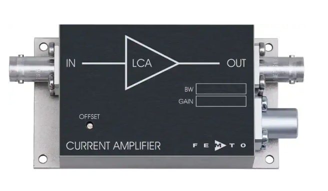
Range features
A high level overview of what this range offers
- Transimpedance from 10^7 to 10^13 V/A: Supports measurements ranging from microampere-level signals down to femtoampere currents.
- Bandwidths from DC to 400 kHz: Allows the response speed to be matched to the measurement task.
- Input noise down to 0.18 fA/√Hz: Supports detection of very small current changes in low-frequency applications.
- Stable response with detector capacitance: Maintains the stated bandwidth with capacitances up to 10 nF, or 1 nF for the 400 kHz model.
- Gain flatness of ±0.1 dB: Provides consistent current-to-voltage conversion across the passband of fixed-bandwidth variants.
- Adjustable input offset compensation: Allows detector background current and system offset to be trimmed before measurement.
- ±10 V output range: Provides a practical signal level for oscilloscopes, data acquisition cards and lock-in amplifiers.
- 50 Ω output impedance: Supports stable connection to common laboratory instruments when used with the specified high-impedance load.
- Short-circuit-protected output: Helps protect the output stage during connection and system integration.
- EMI-shielded metal enclosure: Limits interference coupling into sensitive low-current measurements.
- BNC input and output connectors: Simplify connection to detectors and measurement equipment.
- Compact preamplifier format: Enables placement close to the signal source, shortening the sensitive input path.
Downloads
for LCA Series Current/Transimpedance Low-noise Amplifiers
What’s in this range?
All the variants in the range and a comparison of what they offer
Series specifications
| Parameter | Specification |
|---|---|
Number of variants | 14 |
Gain configuration | Fixed by model; LCA-2-10T provides two selectable gains |
Transimpedance range | 1 × 10^7 to 1 × 10^13 V/A |
Gain accuracy | ±1% for LCA-30 through LCA-400K variants; ±2% for LCA-2-10T |
Lower cut-off frequency | DC |
Upper cut-off frequency | 0.1 Hz to 400 kHz, depending on model and filter setting |
LCA-2-10T filter settings | 2 Hz, 0.3 Hz and 0.1 Hz |
Gain flatness | ±0.1 dB for LCA-30 through LCA-400K variants |
Equivalent input noise current | 0.18 to 65 fA/√Hz, depending on model and test frequency |
Equivalent input noise voltage | 5 to 90 nV/√Hz for LCA-30 through LCA-400K variants, depending on model and test frequency |
Rise and fall time | 1 µs to 5 s, depending on model and filter setting |
Input bias current | 20 fA typical and 30 fA maximum for variants up to 200 Hz; 2 pA typical from 1 kHz upwards |
Input bias drift factor | Model-dependent; 1.7 to 2.3 per 10 K, with 2 per 10 °C for LCA-2-10T |
Offset compensation range | ±50 fA to ±300 nA, adjustable by trimmer |
Maximum linear input current | ±1 pA to ±1 µA, depending on gain and model |
Input offset voltage | Less than 0.5 mV for variants up to 200 Hz; less than 1 mV from 1 kHz upwards |
DC input impedance | 1 kΩ virtual in parallel with 5 pF up to 200 Hz; 50 Ω virtual in parallel with 5 pF from 1 kHz upwards |
Detector capacitance | Stated bandwidth and response maintained up to 10 nF; up to 1 nF for LCA-400K-10M |
Output voltage | ±10 V with the required load |
Required output load | Greater than 10 kΩ for standard variants; at least 1 MΩ for LCA-2-10T |
Output impedance | 50 Ω |
Maximum linear output current | ±10 mA |
Output protection | Short-circuit protected |
Supply voltage | ±15 V DC |
Typical supply current | ±15 to ±45 mA, depending on model |
Absolute maximum supply voltage | ±20 V for LCA-2-10T; ±22 V for other variants |
Absolute maximum input voltage | ±5 to ±10 V, depending on model |
LCA-2-10T transient input protection | ±2 kV human body model |
Operating temperature | 0 to +60 °C |
Storage temperature | −40 to +100 °C |
Enclosure material | Nickel-plated AlMg4.5Mn |
Weight | 210 g |
Signal connectors | BNC input and BNC output |
Power connector | LEMO Series 1S, three-pin fixed socket |
Power connector pinout | Pin 1: +15 V; pin 2: −15 V; pin 3: ground |
Variant comparison
| Specification | LCA-2-10T | LCA-30-1T | LCA-30-200G | LCA-200-100G | LCA-200-10G | LCA-1K-5G | LCA-2K-2G | LCA-4K-1G | LCA-10K-500M | LCA-20K-200M | LCA-40K-100M | LCA-100K-50M | LCA-200K-20M | LCA-400K-10M |
|---|---|---|---|---|---|---|---|---|---|---|---|---|---|---|
Bandwidth from DC | 2 Hz* | 30 Hz | 30 Hz | 200 Hz | 200 Hz | 1 kHz | 2 kHz | 4 kHz | 10 kHz | 20 kHz | 40 kHz | 100 kHz | 200 kHz | 400 kHz |
Input noise current | 0.18 fA/√Hz | 0.5 fA/√Hz | 0.5 fA/√Hz | 1.5 fA/√Hz | 1.5 fA/√Hz | 3 fA/√Hz | 4.5 fA/√Hz | 6.5 fA/√Hz | 10 fA/√Hz | 14 fA/√Hz | 19 fA/√Hz | 30 fA/√Hz | 40 fA/√Hz | 65 fA/√Hz |
Transimpedance | 1 × 10^12 or 1 × 10^13 V/A | 1 × 10^12 V/A | 2 × 10^11 V/A | 1 × 10^11 V/A | 1 × 10^10 V/A | 5 × 10^9 V/A | 2 × 10^9 V/A | 1 × 10^9 V/A | 5 × 10^8 V/A | 2 × 10^8 V/A | 1 × 10^8 V/A | 5 × 10^7 V/A | 2 × 10^7 V/A | 1 × 10^7 V/A |
Rise and fall time | 200 ms* | 12 ms | 12 ms | 2 ms | 2 ms | 400 µs | 200 µs | 100 µs | 40 µs | 20 µs | 10 µs | 4 µs | 2 µs | 1 µs |
*The comparison uses the 2 Hz setting of the LCA-2-10T. This model also provides 0.3 Hz and 0.1 Hz settings with respective rise and fall times of 1 s and 5 s.
FAQs
for LCA Series Current/Transimpedance Low-noise Amplifiers
Start with the maximum expected detector current and the required signal bandwidth, then choose enough transimpedance to use the recording instrument’s input range without clipping. The range extends from 1 × 10^13 V/A at the low-frequency end to 1 × 10^7 V/A at 400 kHz, so gain and measurement speed trade directly across the available models. Maximum linear input current varies from ±1 pA at the LCA-2-10T’s highest gain to ±1 µA for the LCA-400K-10M. Allow headroom for detector dark current, DC background, offset and transient peaks. In practice, the slowest model that still passes the required signal dynamics will normally provide the lower input noise and higher conversion gain.
The stated bandwidth and frequency response are maintained with detector capacitance up to 10 nF for all variants except the LCA-400K-10M, which is specified up to 1 nF. This reduces the need for external frequency compensation and helps avoid gain peaking when working with capacitive detectors. It does not make cable capacitance irrelevant, because amplifier voltage noise can still be converted into frequency-dependent input current noise through the combined detector and cable capacitance. Keep the detector-to-input cable short wherever possible. For runs longer than one metre in a mechanically stable installation, a low-capacitance cable can help control this additional noise contribution.
The LCA-2-10T is not limited to one fixed transimpedance, as it provides selectable gains of 1 × 10^12 and 1 × 10^13 V/A. It also offers low-pass settings of 2 Hz, 0.3 Hz and 0.1 Hz, corresponding to rise and fall times of 0.2 s, 1 s and 5 s. Equivalent input noise is 0.18 fA/√Hz at 0.2 Hz, while the maximum linear input is ±10 pA at 10^12 V/A or ±1 pA at 10^13 V/A. Its output requires a load of at least 1 MΩ. This variant is therefore suited to very small DC or slowly changing currents where sensitivity is more important than response speed.
The output provides a ±10 V signal range with a 50 Ω source impedance and a maximum linear output current of ±10 mA. Standard variants require a receiving load greater than 10 kΩ, while the LCA-2-10T requires at least 1 MΩ. A 50 Ω termination would reduce the output voltage and fall outside the stated operating conditions, so the receiving instrument should normally be set to its high-impedance input mode. Configure the ADC or oscilloscope range to accommodate both signal polarity and residual DC offset. A well-shielded output cable can also help prevent electromagnetic interference from entering the downstream acquisition system.
Input bias current, detector dark current and external leakage must all be included in the DC error and overload budget. Variants with bandwidths up to 200 Hz specify an input bias current of 20 fA typical and 30 fA maximum, while models from 1 kHz upwards specify 2 pA typical. The adjustable offset compensation range varies by model from ±50 fA to ±300 nA. Adjustment should be performed after thermal settling, with the intended detector, cabling and grounding arrangement connected. If the background current approaches the model’s maximum linear input current, choose a lower transimpedance rather than relying on offset compensation to recover overload margin.
Photovoltaic operation is appropriate when low dark current is the priority and the required response speed is modest. Photoconductive operation applies reverse bias to the detector and can reduce detector capacitance, making it suitable where a faster response is required and additional dark current can be tolerated. The illustrated biased-detector arrangement uses an additional ceramic bypass capacitor of approximately 100 nF close to the detector. Bias source noise, insulation leakage and earthing become increasingly important when measuring picoampere or femtoampere currents. The final choice should therefore be checked against the selected amplifier bandwidth, detector capacitance and acceptable DC background current.
All variants operate from a ±15 V DC supply connected through a three-pin LEMO socket, with pin 1 assigned to +15 V, pin 2 to −15 V and pin 3 to ground. Typical supply current ranges from ±15 mA to ±45 mA depending on the variant, so the supply should include suitable operating margin. The LCA-2-10T specifically calls for a supply capability of at least ±50 mA. The operating temperature range is 0 to +60 °C, while storage is permitted from −40 to +100 °C. A clean dual-rail supply and a deliberate earthing arrangement are important because supply interference or ground loops can obscure the low-level signal being measured.
A low-noise input cable is preferred where the cable may move or be exposed to vibration, because triboelectric charge generated in ordinary coaxial cable can produce current pulses in the picoampere or nanoampere range. If the input run must exceed one metre and the installation is mechanically undisturbed, a low-capacitance cable can reduce capacitively induced noise. The source-to-amplifier path should still be kept as short as practical, as the module is intended for placement close to the detector. A shielded 50 Ω RF cable is suitable for the output connection and helps control electromagnetic pickup. The 50 Ω cable impedance does not mean that a 50 Ω termination should be added to the amplifier output.