United Kingdom
Design challenges – understanding the variety of core parameters which affect your RCD design

There are different types of RCDs, but the function remains the same to detect small currents (AC and/or DC) and immediately interrupt the current circuit when specific parameters have been met. In each RCD a differential current transformer is used as a sensor to transfer the failure current (total sum of all currents through all phases which means the total current flowing to ground) when it exceeds a certain limit, this power triggers a relay which interrupts the circuit. The trigger (tripping) current depends on application and different norms; for domestic devices it’s usually 30 mA AC. The same principle is used in an industrial environment, or recently for EV charging.
There are a variety of parameters which need to be considered when designing the designated differential current transformer, including current type (AC and/or DC) and tripping point, nominal current operating range, operating temperature range, etc., and resulting core material choice and core design are key to making sure your RCD design works exactly under all operational conditions. The two most common types of RCD are AC-type which is designed to detect and respond to AC sinusoidal wave only, and A-Type which can detect and respond to AC sinusoidal, as well as pulsating DC components. Both work without external power supply, unlike B-type RCDs which have to detect currents between DC and about 1 kHz.
Determining your requirements for AC-type RCDs
Usually a RCD core is specified by a voltage range at a test current around 30 mA. More interesting for function is the question: at which current the tripping voltage is achieved?
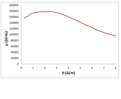
In an AC-type RCD, your trigger point needs to match the core materials highest permeability. Which means using cores with a round (R-) hysteresis loop, and a maximum permeability of 500.000 forming a pronounced peak in the µ vs I curve around 10 mA/cm. This means that if the core diameter is about 1 cm then the tripping point would be 30 mA. For smaller currents, permeability drops down significantly by a factor of 2 or even more. This µ vs I behavior results in low voltage for currents below the trigger point, with a sharp increase of the voltage (hence: power) approaching the trigger point. It’s easily seen that the tolerance of the resulting tripping current is much smaller than the voltage tolerance of the core – if the core material and geometry match the tripping current.
Acal BFi offers nanocrystalline cores under Acal BFi kOr brand to complete our core portfolio.
Determining your requirements for A-type RCDs
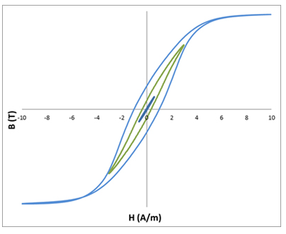
Increasing number of devices use currents with DC part (half wave rectified, phase cut voltage control, DC pulse…), have changed the requirements and norms in A type RCDs: they now have to be tolerant against superimposed DC currents of few mA. It means that the AC current controlling the output power doesn’t excite the core symmetrically. The hysteresis loop is shifted along the field axis. In extreme case the excitation is unipolar or even pulses, which is reflected by the typical test procedure: the RCD must trip not only at a certain sine wave current, but also at a rectified current and even at half wave rectified. Back to the hysteresis loop it means that a sufficient voltage and hence permeability must be achieved both, for symmetric loops and for a loop starting in remanence point. The difference between these conditions becomes significant at high remanence because the slope of the B-H curve is flat when starting from remanence towards operation point. Consequently, material with low remanence is needed; ideally also with a linear B-H loop at least between the tripping points. This is reflected by a so-called flat (F-) hysteresis loop. There is no pronounced maximum permeability peak anymore, however, requiring narrow tolerances for the voltage, generated by permeability and cross-section. A good compromise for high permeability with acceptable tolerances, and high linearity / low remanence is achieved at permeability level around 150.000 – and even beyond.
Temperature behaviour
Another challenge is the temperature behaviour: RCDs need to work independent of the ambient temperature and load between -25°C and 100°C, even though the core materials may have a pronounced µ vs T dependence. The material properties can be controlled, within a very limited range, independently from permeability vs current behaviour. It’s worth to note that a vanishing temperature dependence is not required in any case – a certain slope can be used to compensate temperature dependence of copper resistance of secondary winding, or any capacitors in the device.
Finding the right material for your RCD design:
Suitable cores for both AC and A-type RCDs requirements can be found among the 80%NiFe and nanocrystalline materials, in which the Hysteresis loop can be tailored by heat treatment in magnetic fields resulting in well-defined R or F loops.
In the last decade, NiFe material has been substituted almost completely by Fe-based nanocrystalline material, triggered by an increase in nickel prices two decades ago, and the higher saturation induction and permeability potential of nanocrystalline material which enables engineers to create smaller designs.
Acal BFi offers nanocrystalline cores under Acal BFi kOr brand to complete our core portfolio.
We offer toroidal cores of our kOr 120 and kOr 118 materials for this application. These are Fe-base nanocrystalline materials comparable with VITROPERM® (VAC) and Nanoperm® (Magnetec):
kOr 120 material is designed for applications which need µmax 20.000-100.000 at 10 kHz, but is has much higher permeability and good linearity up to 300.000 at 50 Hz. Together with a high saturation flux density, low losses and low magnetostriction makes it perfect for high linear RCD cores.
kOr 118 materials are designed for applications which need µmax 100.000-250.000. This material is specifically developed for RCCB and RCD applications with moderate linearity.
Properties available:
- BS = 1,2 T
- µmax = 20.000 – 250.000 @ 50 Hz
- Bdyn / Bmax ≥ 0,85 (µmax up to 180.000) and ≥ 0,8 (µmax up to 250.000)
- λS < 1 ppm
- temperature dependence of permeability adjustable in own or custom plastic cases, fixed with foam rings
Actual choice of a material is made by our designers depend on specification of the core.
Typical hysteresis curves and µ vs. H curve for a kOr 120 RCD core with µmax = 180.000