CMS390 series orthogonal combi-sensor
- Technology
- Accelerometers and tilt sensors
- Partner
- Silicon Sensing
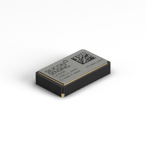
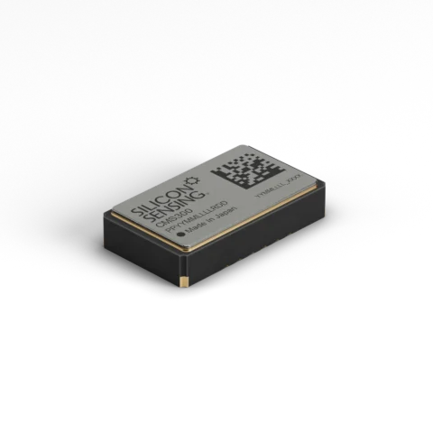
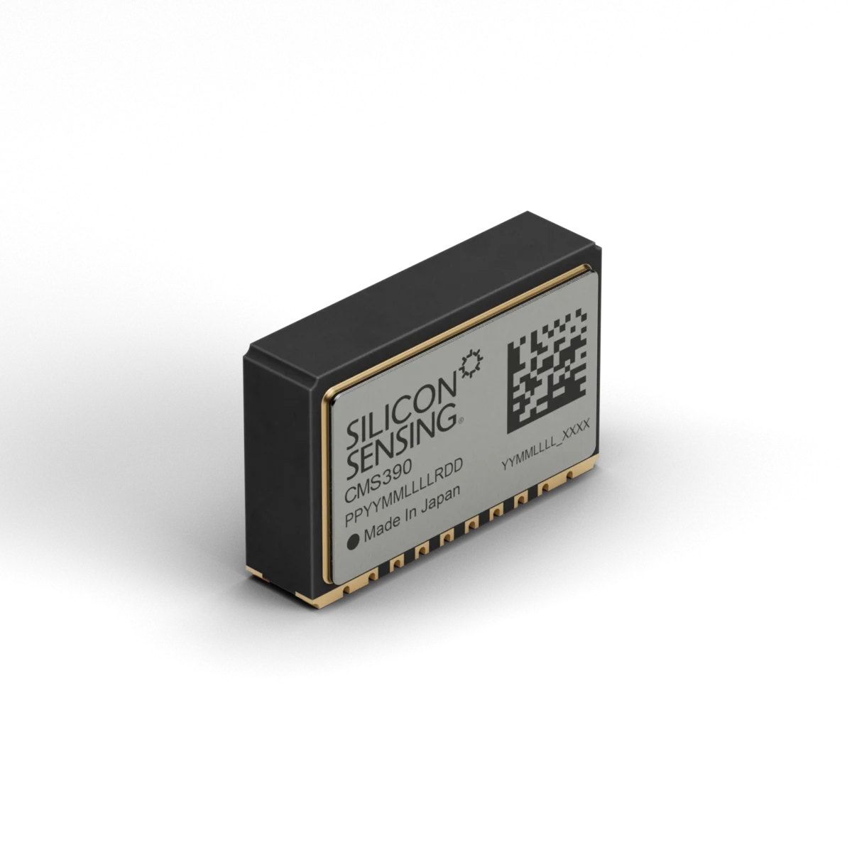
The CMS390 combines a vibrating-ring gyroscope, a dual-axis accelerometer and a dedicated control ASIC in one ceramic LCC surface-mount package. Its orthogonal mounting orientation places the angular-rate Z axis parallel to the host PCBA, with the acceleration X axis parallel to the board and the Y axis perpendicular to it. This arrangement suits custom IMUs, AHRS, inclinometers, levelling systems, navigation equipment, measurement and control systems, and robotics.
The sensor can also be used alongside the flat CMS300 variant when complementary sensing orientations are required on one PCBA. Selectable angular-rate ranges of ±150°/s and ±300°/s are complemented by acceleration ranges of ±2.5g and ±10g. Bandwidth can be configured independently for each channel to match the application’s dynamics and noise requirements. Operation from a nominal 3.3 V supply, an 8 mA maximum operating current and a −40°C to +125°C temperature range supports compact embedded inertial designs.
Range features
A high level overview of what this range offers
- Single-axis gyroscope and dual-axis accelerometer: Measures angular rate and two linear-acceleration axes in one component.
- Orthogonal side mounting: Supports in-plane angular-rate sensing and out-of-plane acceleration measurement from one PCBA.
- Selectable ±150°/s or ±300°/s rate range: Allows resolution and measurement headroom to be matched to the application.
- Selectable ±2.5g or ±10g acceleration range: Accommodates low-g motion measurement and higher dynamic inputs.
- Independent channel bandwidth selection: Enables separate response settings for the gyroscope and each acceleration axis.
- Digital SPI interface: Provides angular-rate, acceleration, temperature and status data to the host processor.
- Built-in commanded self-test: Supports functional checking of the rate and acceleration channels.
- Integral temperature sensor: Supplies data for host-level thermal compensation.
- 8 mA maximum operating current: Limits the load placed on compact 3.3 V systems.
- −40°C to +125°C operation: Supports equipment exposed to wide ambient-temperature ranges.
- Hermetically sealed ceramic LCC package: Provides a surface-mount format resistant to temperature and humidity exposure.
- RoHS compliance: Supports component selection for applicable restricted-substance requirements.
What’s in this range?
All the variants in the range and a comparison of what they offer
Unless otherwise stated, detailed performance values apply with a 3.15 V to 3.45 V supply at an ambient temperature of +25°C. Over-temperature values refer to −40°C to +125°C unless a narrower range is stated in the notes.
Specifications
| Category | Parameter | Minimum | Typical | Maximum | Notes |
|---|---|---|---|---|---|
General | Sensing arrangement | — | 1-axis angular rate and 2-axis linear acceleration | — | Z-rate axis; X and Y acceleration axes |
General | Mounting orientation | — | Orthogonal, side mounted | — | Z axis parallel to host PCBA |
General | Package | — | Hermetically sealed ceramic LCC | — | Surface-mount package |
General | Dimensions | — | 10.4 × 6.7 × 2.7 mm | — | Physical package dimensions |
General | Mass | — | 0.6 g | — | — |
Rate channel | Dynamic range | — | ±150°/s or ±300°/s | — | User selectable |
Rate channel | Resolution | — | 0.005°/s at ±150°/s; 0.01°/s at ±300°/s | 0.05°/s | 204.8 LSB/(°/s) or 102.4 LSB/(°/s) |
Rate channel | Scale-factor variation over temperature | — | <±1% | ±2.0% | — |
Rate channel | Scale-factor non-linearity | — | <±0.15°/s at ±150°/s; <±0.3°/s at ±300°/s | <±0.30°/s at ±150°/s; <±0.75°/s at ±300°/s | Deviation from best-fit straight line |
Rate channel | Bias variation with temperature | — | ±1.0°/s | ±1.75°/s | — |
Rate channel | Bias switch-on repeatability | — | ±0.03°/s | ±0.15°/s | At constant ambient temperature |
Rate channel | Bias drift after switch-on | — | ±0.02°/s | ±0.2°/s | At constant ambient temperature |
Rate channel | Bias instability | — | 10°/hr | — | — |
Rate channel | Angular random walk | — | 0.40°/√hr | — | — |
Rate channel | Acceleration sensitivity | — | ±0.025°/s/g | ±0.1°/s/g | — |
Rate channel | In-band noise | — | 0.06°/s RMS | 0.1°/s RMS | Measured to 45 Hz |
Rate channel | Selectable bandwidths | 40, 50, 80 or 95 Hz | 45, 55, 90 or 110 Hz | 50, 60, 100 or 125 Hz | −3 dB, second-order response |
Rate channel | Maximum phase delay | — | — | 11 ms | At 45 Hz bandwidth |
Rate channel | Mechanical operating resonance | — | 22 kHz | — | — |
Acceleration channels | Dynamic range | — | ±2.5g or ±10g | — | Independently selectable |
Acceleration channels | Resolution | — | 0.079 mg at ±2.5g; 0.313 mg at ±10g | 1 mg | 12,800 LSB/g or 3,200 LSB/g |
Acceleration channels | Scale-factor variation over temperature | — | ±1% | ±2.5% | — |
Acceleration channels | Scale-factor non-linearity | — | 3 mg at ±2.5g; 5 mg at ±10g | 12.5 mg at ±2.5g; 50 mg at ±10g | Error proportional to acceleration cubed |
Acceleration channels | Orthogonality | — | ±0.1° | — | Relative alignment between acceleration axes |
Acceleration channels | In-band noise | — | 1 mg RMS | 2 mg RMS | Measured in 45 Hz bandwidth |
Acceleration channels | Velocity random walk | — | <0.05 m/s/√hr | — | — |
Acceleration channels | Bias instability | — | <0.05 mg | — | — |
Acceleration channels | Selectable bandwidths | 40, 55, 85 or 170 Hz | 45, 62, 95 or 190 Hz | 50, 70, 105 or 210 Hz | −3 dB, second-order response |
Acceleration channels | Maximum phase delay | — | — | 10 ms | At 45 Hz bandwidth |
Acceleration channels | Mechanical resonance | — | 2.9 kHz | — | MEMS resonance |
±2.5g mode | Turn-on bias | — | — | ±30 mg | At 25 ±5°C |
±2.5g mode | Bias variation with temperature | — | — | ±30 mg | −40°C to +85°C, normalised to +25°C |
±2.5g mode | Bias switch-on repeatability | — | ±0.3 mg | ±1.5 mg | At constant temperature |
±10g mode | Turn-on bias | — | — | ±75 mg | At 25 ±5°C |
±10g mode | Bias variation with temperature | — | ±50 mg | ±75 mg | −40°C to +85°C, normalised to +25°C |
±10g mode | Bias switch-on repeatability | — | ±0.3 mg | ±2.0 mg | At constant temperature |
Temperature sensor | Scale factor | 10.67 LSB/°C | 11 LSB/°C | 11.33 LSB/°C | — |
Temperature sensor | Offset | −20°C | — | +20°C | — |
Temperature sensor | Repeatability | −5°C | — | +5°C | — |
Start-up | Time to full performance | — | 150 ms | 300 ms | — |
Rate CBIT | Response at +25°C | +54°/s at ±150°/s; +90°/s at ±300°/s | +64°/s; +107°/s | +74°/s; +125°/s | Commanded built-in test |
Acceleration CBIT | Response at +25°C | +1.0g at ±2.5g; +4.7g at ±10g | +1.25g; +6.2g | +1.50g; +7.7g | Commanded built-in test |
Alignment | Rate-sensor misalignment | — | — | ±3% | Alignment to package mounting face |
Alignment | Acceleration-sensor misalignment | — | — | ±3% | Alignment to package |
Environment | Operating temperature | −40°C | — | +125°C | — |
Environment | Storage temperature | −55°C | — | +150°C | — |
Environment | Humidity | — | — | 90% RH | Non-condensing |
Environment | Vibration rectification error | — | 0.001°/s/g² RMS | 0.003°/s/g² RMS | 8.85 g RMS random stimulus, 10 Hz to 5 kHz |
Electrical | Supply-voltage range | 2.7 V | 3.3 V | 3.6 V | — |
Electrical | Full-specification supply range | 3.15 V | 3.3 V | 3.45 V | — |
Electrical | Operating current | — | — | 8.0 mA | After start-up |
Interface | Data interface | — | Digital SPI | — | Rate, acceleration, temperature and status data |
Interface | SPI message rate | 1 Hz | 1 kHz | 10 kHz | — |
Interface | SPI clock rate | 100 kHz | 1 MHz | 7 MHz | — |
Compliance | Restricted substances | — | RoHS compliant | — | — |
Absolute limit | Powered angular velocity | — | — | 150,000°/s | Saturated output |
Absolute limit | Powered linear acceleration | — | — | 1,000g | 1 ms half-sine pulse |
Absolute limit | Unpowered linear acceleration | — | — | 10,000g | 0.5 ms pulse |
Absolute limit | Operating linear acceleration | — | — | 95g | 6 ms half-sine pulse |
Absolute limit | ESD protection | — | — | 2 kV HBM; 250 V CDM | — |
Service life | Unpowered life | 15 years | — | — | — |
Service life | Powered life | 12,000 hours | — | — | — |
Variant and package comparison
| Part number | Sensing axes | Mounting relationship | Angular-rate range | Acceleration range | Interface | Overall dimensions | Supply voltage |
|---|---|---|---|---|---|---|---|
CMS300 | Single-axis Z rate; dual-axis X/Y acceleration | Z axis perpendicular to host PCBA | ±150°/s or ±300°/s | ±2.5g or ±10g | Digital SPI | 10.4 × 6.0 × 2.2H mm | 2.7 to 3.6 V |
CMS390 | Single-axis Z rate; dual-axis X/Y acceleration | Z axis parallel to host PCBA | ±150°/s or ±300°/s | ±2.5g or ±10g | Digital SPI | 10.4 × 2.7 × 6.7H mm | 2.7 to 3.6 V |
FAQs
for CMS390 series orthogonal combi-sensor
The CMS390 is designed for orthogonal side mounting rather than flat placement. In this orientation, its angular-rate Z axis and acceleration X axis are parallel to the PCBA, while the acceleration Y axis is perpendicular to the board. This configuration can simplify an all-axis sensor arrangement when the device is combined with a flat CMS300 on the same assembly. The maximum stated rate- and acceleration-sensor misalignment is ±3% relative to the package or mounting face. Designs requiring tighter alignment should use controlled placement fixtures, assembly inspection and processor-based correction of residual cross-axis error.
The appropriate settings depend on the maximum expected motion and the required signal resolution. The ±150°/s rate range provides 0.005°/s typical resolution, while the ±300°/s setting provides 0.01°/s resolution and more headroom for faster rotation. Acceleration can be set to ±2.5g with 0.079 mg typical resolution or ±10g with 0.313 mg typical resolution. Nominal gyroscope bandwidths are 45, 55, 90 and 110 Hz, while the acceleration channels provide 45, 62, 95 and 190 Hz settings. Each channel can be configured independently, allowing bandwidth to be limited where lower noise is more important than fast transient response.
The sensor operates from 2.7 to 3.6 V, although the complete performance specification applies within 3.15 to 3.45 V. Both start-up and steady-state current are specified at a maximum of 8 mA, excluding current used to charge external decoupling components. Full performance is reached after 150 ms typically and 300 ms at maximum. The SPI clock can run from 100 kHz to 7 MHz, with message rates from 1 Hz to 10 kHz. The host processor should allow the start-up interval to complete before relying on calibrated data and should select an update rate compatible with the configured sensor bandwidth.
The CMS390 operates from −40°C to +125°C, but some detailed accelerometer bias limits are stated over the narrower −40°C to +85°C interval. Gyroscope bias variation with temperature is ±1.0°/s typical and ±1.75°/s maximum, while scale-factor variation is below ±1% typical and ±2.0% maximum. The integral temperature channel has an 11 LSB/°C typical scale factor, with offset and repeatability limits of ±20°C and ±5°C respectively. These values make the temperature output suitable for compensation rather than precision ambient-temperature measurement. Applications with strict attitude or navigation accuracy should characterise the complete mounted assembly and apply host-level correction across the expected thermal profile.
The gyroscope has 0.06°/s typical in-band RMS noise measured to 45 Hz, with a 0.1°/s maximum and an angular random walk of 0.40°/√hr. Its stated bias instability is 10°/hr, so uncompensated integration will accumulate angular error over time. The acceleration channels have 1 mg typical and 2 mg maximum RMS noise in a 45 Hz bandwidth, together with velocity random walk below 0.05 m/s/√hr. These figures suit motion measurement, stabilisation, tilt sensing and lower-cost attitude systems, but filtering and calibration are still required. Final system error will also depend on bandwidth, sample rate, mounting alignment, vibration and the fusion algorithm used by the host processor.
The package measures 10.4 × 6.7 × 2.7 mm and has a mass of approximately 0.6 g. Because the device is mounted on its side, placement control is more critical than for a conventional flat LCC component, particularly where axis perpendicularity influences system accuracy. The operating range is −40°C to +125°C, storage is permitted from −55°C to +150°C and humidity is limited to 90% RH non-condensing. The sensor is rated for 95g operating acceleration over a 6 ms half-sine pulse and 1,000g powered survival over 1 ms. PCB layout, soldering processes, mechanical support and post-assembly alignment checks should therefore be included in the integration plan.
The commanded built-in test applies known responses to the gyroscope and accelerometer channels so that the host can check whether each sensing path is operating within its expected window. At +25°C, the typical gyroscope response is +64°/s in the ±150°/s range and +107°/s in the ±300°/s range. The accelerometer response is typically +1.25g in the ±2.5g range and +6.2g in the ±10g range. Defined response variation is also provided across −40°C to +125°C, allowing temperature-aware pass and fail thresholds to be implemented. Built-in test is useful at start-up and during maintenance, but it does not replace application-level calibration or verification of mechanical alignment.