CAS290 series (dual-axis, orthogonal) high-perfomance linear accelerometers
- Technology
- Accelerometers and tilt sensors
- Partner
- Silicon Sensing
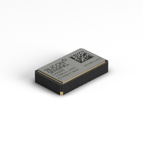
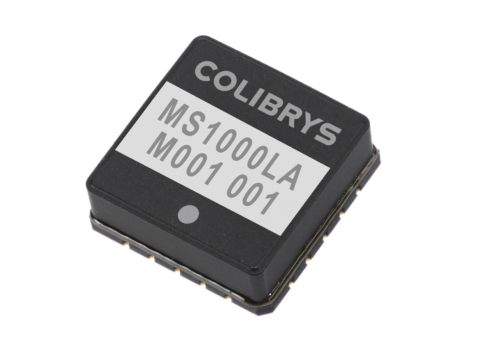
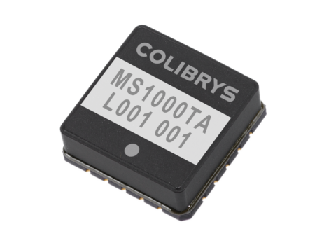
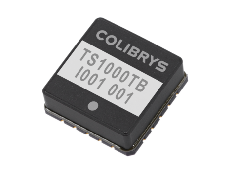
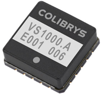
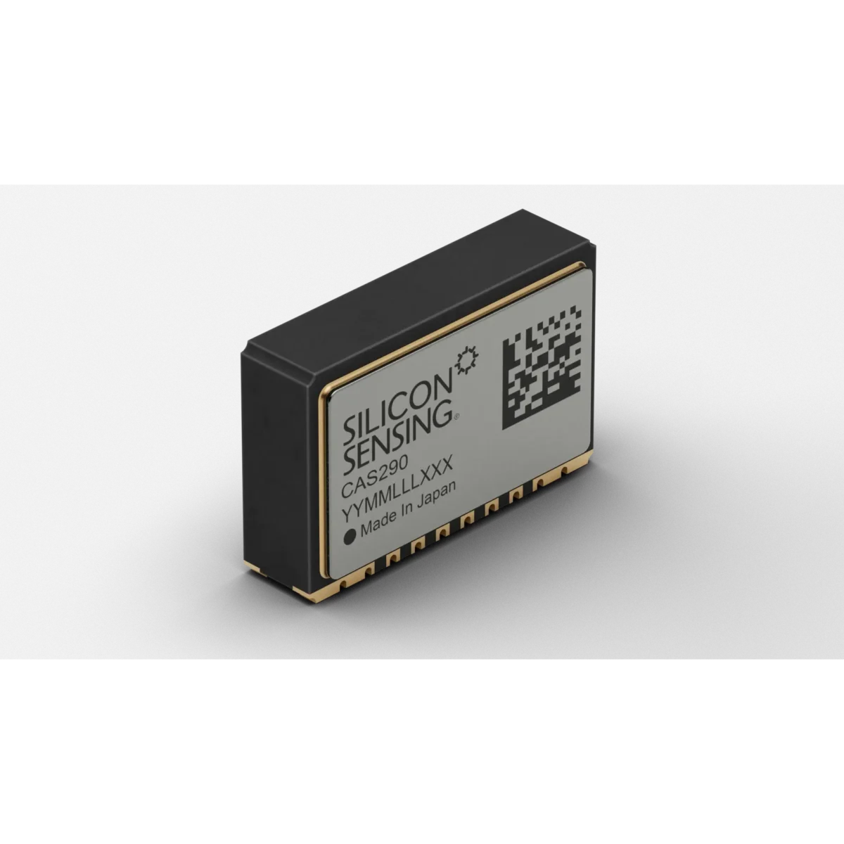
The CAS290 series MEMS accelerometer measures linear acceleration along two axes from an orthogonally mounted surface-mount package. Its side-mounted format supports axis arrangements that would otherwise require a perpendicular PCB. The series comprises the CAS291, CAS292, CAS293, CAS294 and CAS295, covering acceleration ranges from ±0.85 g to ±96 g. Acceleration and temperature data are available through analogue and digital SPI interfaces, while the digital interface also provides built-in test information.
Typical applications include attitude and heading reference systems, inertial measurement units, platform stabilisation, drilling guidance, surveying, navigation, transport systems and levelling equipment. The hermetically sealed ceramic LCC measures 10.4 × 6.7 × 2.7 mm and is intended for direct PCBA mounting. A -40 °C to +125 °C operating range and typical current consumption of 3 mA support installations with wide temperature exposure and defined power constraints.
Range features
A high level overview of what this range offers
- Five measurement ranges: Select from ±0.85 g, ±2.5 g, ±10 g, ±30 g and ±96 g to match sensitivity and measurement headroom to the application.
- Orthogonal dual-axis construction: Supports multi-axis sensing arrangements on one PCBA without requiring a separate perpendicular board.
- Analogue and digital SPI outputs: Accommodates external analogue acquisition and direct digital processing architectures.
- Acceleration and temperature outputs: Supplies X-axis, Y-axis and temperature data for measurement, compensation and system diagnostics.
- Digital built-in test status: Provides an additional indication of sensor operating condition through the SPI interface.
- Wide measurement bandwidth: Delivers digital bandwidth above 170 Hz and analogue bandwidth above 250 Hz.
- Defined low-power operation: Uses a 3.3 V nominal supply with typical current consumption of 3 mA.
- Hermetically sealed ceramic LCC: Provides a compact, surface-mountable package suitable for the stated temperature and humidity limits.
- Fast start-up: Becomes operational within a maximum of 20 ms after power-up.
- High operating-shock tolerance: Withstands a 1,000 g, 1 ms half-sine operating shock.
- Wide operating temperature range: Supports operation from -40 °C to +125 °C.
- RoHS compliant: Supports material-compliance requirements for electronic assemblies.
What’s in this range?
All the variants in the range and a comparison of what they offer
CAS290 series-wide specifications
| Parameter | Specification |
|---|---|
Variants | CAS291, CAS292, CAS293, CAS294 and CAS295 |
Sensor technology | Silicon MEMS dual-axis linear accelerometer with dedicated control ASIC |
Acceleration axes | 2 |
Mounting orientation | Orthogonal, side-mounted |
Package | Hermetically sealed ceramic LCC, surface mountable |
Outputs | Analogue ratiometric and four-wire digital SPI |
Output data | X-axis acceleration, Y-axis acceleration and temperature |
Diagnostic output | Built-in test status through the digital interface |
Available measurement ranges | ±0.85 g, ±2.5 g, ±10 g, ±30 g and ±96 g |
Functional supply range | 2.7 V to 3.6 V |
Full-specification supply range | 3.15 V to 3.45 V |
Nominal supply voltage | 3.3 V |
Typical current consumption | 3 mA |
Digital bandwidth | Above 170 Hz |
Analogue bandwidth | Above 250 Hz |
Operating temperature | -40 °C to +125 °C |
Storage temperature | -55 °C to +150 °C |
Humidity limit | 90% RH, non-condensing |
Dimensions | 10.4 × 6.7 × 2.7 mm |
Typical mass | 0.6 g |
Maximum start-up time | 20 ms |
Maximum recovery time | 10 ms after over-range or shock |
Typical mounting misalignment | ±25 mrad with suitable soldering fixtures |
Misalignment limits | -40 mrad to +40 mrad |
Typical internal axis orthogonality | 1.7 mrad |
Operating shock | 1,000 g, 1 ms half-sine |
Non-operating shock | 6,500 g, 0.1 ms half-sine for CAS291–CAS293; 10,000 g, 0.1 ms half-sine for CAS294–CAS295 |
ESD protection | 2 kV HBM |
Minimum unpowered life | 15 years |
Minimum powered life | 12,000 hours |
Digital temperature scale factor | 11 lsb/°C |
Digital temperature offset | 2,380 lsb at +25 °C |
Analogue temperature scale factor | 5 mV/°C |
Analogue temperature offset | 1.49 V at +25 °C |
Temperature output repeatability | ±5 °C |
SPI configuration | Four-wire slave, Mode 0 |
SPI message length | 6 bytes / 48 bits |
SPI message rate | 1 Hz minimum, 1 kHz recommended, 10 kHz maximum |
SPI clock rate | 100 kHz minimum, 1 MHz nominal, 8 MHz maximum |
Compliance | RoHS compliant |
Variant comparison
| Specification | CAS291 | CAS292 | CAS293 | CAS294 | CAS295 |
|---|---|---|---|---|---|
Dynamic range | ±0.85 g | ±2.5 g | ±10 g | ±30 g | ±96 g |
Digital scale factor | 33,500 lsb/g | 11,000 lsb/g | 2,800 lsb/g | 1,050 lsb/g | 300 lsb/g |
Analogue scale factor | 1,150 mV/g | 375 mV/g | 96 mV/g | 36 mV/g | 10 mV/g |
Digital / analogue scale-factor error at +25 °C | ±1% / ±1.5% | ±1% / ±1.5% | ±1% / ±1.5% | ±1% / ±1.5% | ±1% / ±1.5% |
Scale-factor variation over temperature | ±1.2% | ±1.2% | ±1.2% | ±1.2% | ±1.2% |
Scale-factor stability over one year | ±1,000 ppm | ±1,000 ppm | ±1,000 ppm | ±1,000 ppm | ±1,000 ppm |
Scale-factor non-linearity | 0.5% FSR | 0.5% FSR | 2% FSR | 2% FSR | 2% FSR |
Bias run-to-run variation at +25 °C | ±0.35 mg | ±0.75 mg | ±0.75 mg | ±3.0 mg | ±8.0 mg |
Bias variation over temperature | ±50 mg | ±50 mg | ±50 mg | ±150 mg | ±500 mg |
Bias stability over one year | ±7.5 mg | ±7.5 mg | ±7.5 mg | ±25 mg | ±75 mg |
Resolution / threshold at 1 Hz | 0.03 mg | 0.10 mg | 0.10 mg | 0.30 mg | 1.0 mg |
Typical noise spectral density | ≤50 µg/√Hz | ≤150 µg/√Hz | ≤150 µg/√Hz | ≤350 µg/√Hz | ≤1,200 µg/√Hz |
Digital / analogue bandwidth |
|
|
|
|
|
Vibration rectification | 0.15 mg/g² at 0.5 g rms | 0.15 mg/g² at 2.0 g rms | 0.15 mg/g² at 8.0 g rms | 0.1 mg/g² at 12 g rms | 0.1 mg/g² at 12 g rms |
Velocity random walk | 0.07 m/s/√h | 0.07 m/s/√h | 0.07 m/s/√h | 0.07 m/s/√h | 0.07 m/s/√h |
FAQs
for CAS290 series (dual-axis, orthogonal) high-perfomance linear accelerometers
Choose the lowest range that still covers normal acceleration, expected transients and an appropriate design margin, because the lower-range variants provide greater output sensitivity and lower measurement thresholds. CAS291 covers ±0.85 g with 33,500 lsb/g, 1,150 mV/g, a 0.03 mg threshold and noise density of no more than 50 µg/√Hz. CAS292 and CAS293 extend the range to ±2.5 g and ±10 g while retaining 0.10 mg thresholds. CAS294 and CAS295 cover ±30 g and ±96 g, but their thresholds rise to 0.30 mg and 1.0 mg respectively. Model worst-case shock and vibration before selecting the range rather than basing the decision solely on nominal acceleration.
Use the analogue output when the host system already includes suitable high-resolution conversion or requires the sensor’s bandwidth above 250 Hz. Its scale factor is ratiometric and varies from 1,150 mV/g on CAS291 to 10 mV/g on CAS295, so ADC range, reference stability and input noise must be considered together. The digital interface offers bandwidth above 170 Hz, direct scale factors from 33,500 to 300 lsb/g and access to temperature and built-in test status. It also avoids adding an external ADC solely for the acceleration channels. The final choice therefore depends on bandwidth, conversion accuracy, processing architecture and the diagnostic data required by the host.
Use a 2.7 V to 3.6 V supply for functional operation, but keep Vdd within 3.15 V to 3.45 V when the stated performance limits must be met. The nominal operating point is 3.3 V, with typical current consumption of 3 mA across the range. Allow up to 20 ms for start-up and up to 10 ms to recover from an over-range or shock event before accepting measurement data. The interface design should follow the defined local decoupling arrangement and keep supply impedance low during start-up. This gives the host a clear power-good and data-valid sequence and avoids treating transient output behaviour as valid acceleration.
The orthogonal package places the two MEMS sense axes in a different orientation from a flat-mounted dual-axis accelerometer. When the side-mounted CAS290 is combined with an in-plane sensing arrangement, three degrees of freedom can be measured on one PCBA without installing a separate perpendicular board. The package measures 10.4 × 6.7 × 2.7 mm and has a typical mass of 0.6 g, so mechanical placement and solder-fixture control remain important. Typical package misalignment is ±25 mrad when suitable fixtures are used, while internal axis orthogonality is 1.7 mrad. System calibration should still resolve the installed axis matrix rather than assume perfect geometric alignment.
The CAS290 series operates from -40 °C to +125 °C and can be stored from -55 °C to +150 °C, with humidity limited to 90% RH under non-condensing conditions. The operating shock rating is 1,000 g for a 1 ms half-sine pulse. Non-operating shock capability is 6,500 g for CAS291 through CAS293 and 10,000 g for CAS294 and CAS295, using a 0.1 ms half-sine pulse. These are limit conditions rather than recommended continuous operating points, and prolonged exposure near absolute ratings can affect performance or reliability. The equipment-level design should therefore include mounting, enclosure and vibration controls appropriate to the actual mechanical environment.
Separate initial offset from repeatability, thermal drift, long-term stability and vibration-induced bias. Bias run-to-run variation ranges from ±0.35 mg on CAS291 to ±8.0 mg on CAS295, while one-year bias stability ranges from ±7.5 mg to ±75 mg. Bias variation across -40 °C to +125 °C is ±50 mg for CAS291–CAS293, ±150 mg for CAS294 and ±500 mg for CAS295. The analogue outputs sit nominally around Vdd/2 and may carry a fixed device offset, while the digital channel has its own bias setting error; both can be reduced through system calibration. The remaining error model should include scale-factor temperature variation of ±1.2% and the stated vibration rectification for the selected range.
The digital interface is a four-wire SPI slave operating in Mode 0, with each transaction carrying six bytes or 48 bits. A 1 kHz message rate and 1 MHz clock are nominal; the supported ranges are 1 Hz to 10 kHz for messages and 100 kHz to 8 MHz for the clock. Sampling above 500 Hz is recommended when aliasing is a concern, although the application must still provide filtering suited to its measurement bandwidth. Separate requests provide X/Y acceleration data or status and temperature data, and the command format can enable commanded built-in test. Data_Out is tri-stated when slave select is high, which supports a shared bus when chip-select timing and checksum handling are implemented correctly.
Because the CAS290 series uses capacitive MEMS sensing, conductive tracks routed beneath the package can introduce an acceleration bias offset. Signal and power routing should therefore be kept away from the package footprint where practical, including connections running towards shared supply star points. If routing beneath the device cannot be avoided, the installed offset should be measured and removed through higher-level system compensation. The centre and side fixing pads are mechanical connections and should be soldered to electrically isolated pads. Controlled placement fixtures, axis-orientation checks and a gravity-based calibration can reduce errors associated with package misalignment and assembly tolerances.