CMS300 (in-plane) single-axis MEMS combi-sensor
- Technology
- Accelerometers and tilt sensors
- Partner
- Silicon Sensing
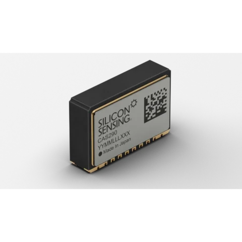
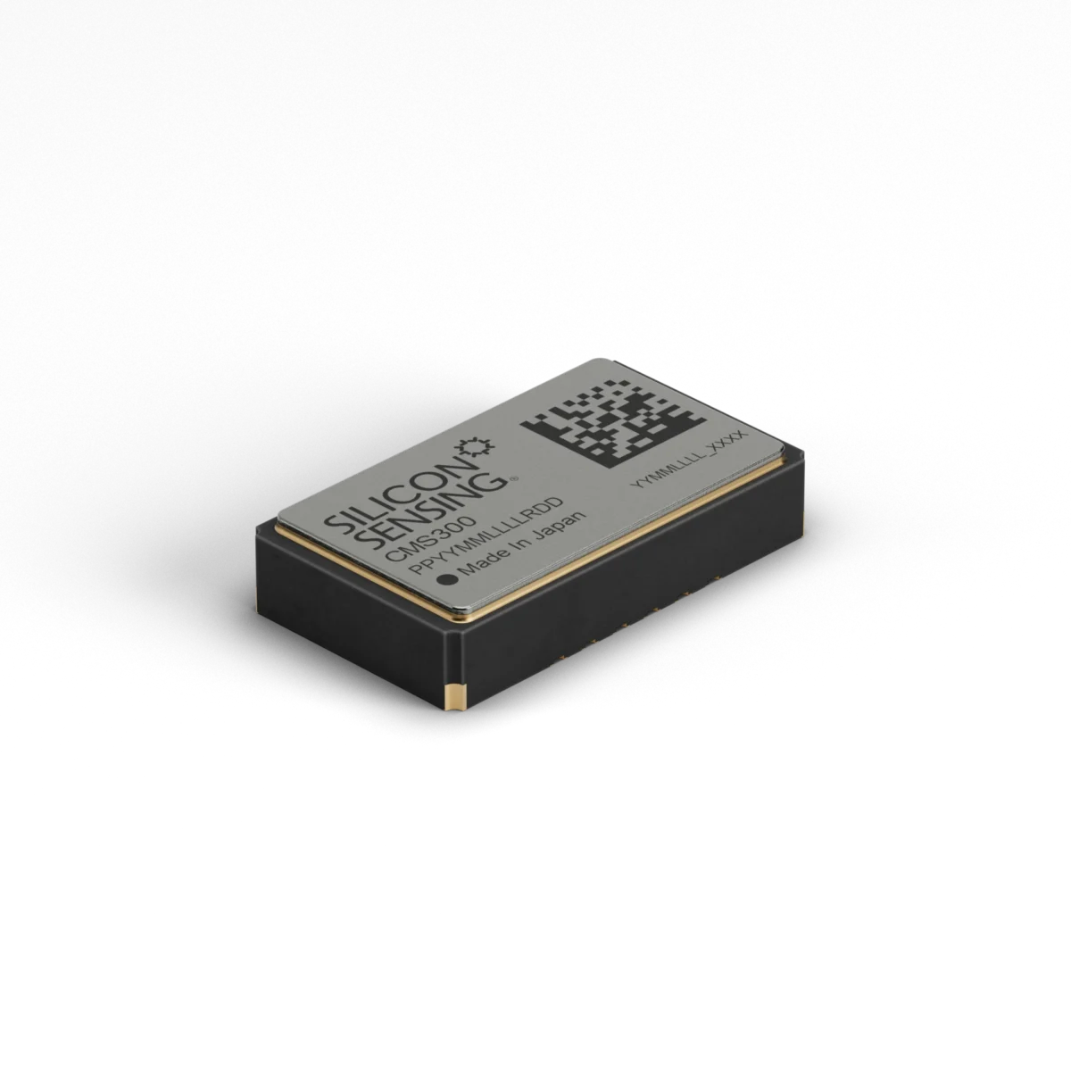
The CMS300 MEMS combi-sensor combines a single-axis vibrating-ring gyroscope, a dual-axis capacitive accelerometer and a dedicated control ASIC in one surface-mount package. Mounted flat on the PCBA, it measures angular rate about the perpendicular Z-axis and linear acceleration along the in-plane X and Y axes. Engineers can independently configure the range and bandwidth of all three sensing channels to suit the expected motion profile. Sensor readings, temperature data, status information and built-in test results are transferred through a four-wire SPI Mode 0 interface.
The device operates from a functional supply of 2.7 V to 3.6 V, with full specified performance from 3.15 V to 3.45 V. Its hermetically sealed ceramic LCC construction and -40°C to +125°C operating range support use in demanding temperature and vibration conditions. Applications include attitude and heading reference systems, inertial measurement units, navigation, levelling, tilt measurement, robotics and industrial control.
Range features
A high level overview of what this range offers
- Single-axis gyroscope and dual-axis accelerometer: Measures three inertial channels within one package.
- In-plane mounting configuration: Provides perpendicular Z-axis rate sensing and parallel X/Y acceleration sensing.
- Selectable angular-rate ranges: Supports ±150°/s and ±300°/s settings to match the expected rotational speed.
- Selectable acceleration ranges: Offers ±2.5g for low-g resolution or ±10g for greater acceleration capacity.
- Independent channel configuration: Allows the range and bandwidth of each sensing axis to be selected separately.
- Selectable gyro bandwidths: Provides nominal settings of 45, 55, 90 or 110 Hz.
- Selectable accelerometer bandwidths: Provides nominal settings of 45, 62, 95 or 190 Hz.
- Four-wire SPI Mode 0 interface: Supports direct digital communication with embedded processors.
- Built-in test and status reporting: Enables start-up checks and system-level diagnostics.
- Integral temperature measurement: Supplies temperature data for monitoring and compensation routines.
- Hermetically sealed ceramic LCC package: Protects the MEMS sensing structures from environmental exposure.
- Maximum 8 mA operating current: Limits the sensor load in low-power embedded systems.
- -40°C to +125°C operation: Supports equipment exposed to broad ambient temperatures.
- RoHS compliant: Supports restricted-substance requirements for electronic assemblies.
What’s in this range?
All the variants in the range and a comparison of what they offer
Unless otherwise stated, performance values apply at +25°C with a 3.15 V to 3.45 V supply. Over-temperature gyroscope values refer to -40°C to +125°C unless a different interval is specified.
Specifications
| Category | Parameter | Minimum | Typical | Maximum or options | Conditions or notes |
|---|---|---|---|---|---|
Configuration | Sensing channels | — | 1 angular-rate axis and 2 acceleration axes | — | Z-axis rate; X/Y acceleration |
Configuration | Axis orientation | — | Z perpendicular to PCBA; X/Y parallel to PCBA | — | Flat, in-plane mounting |
Physical | Package | — | Hermetically sealed ceramic LCC | — | Surface-mount construction |
Physical | Dimensions | — | 10.4 × 6.0 × 2.2 mm | — | Overall package size |
Physical | Mass | — | 0.4 g | — | Sensor only |
Physical | Gyro and accelerometer misalignment | — | — | ±1.5% | Relative to the package mounting references |
Gyroscope | Angular-rate range | — | — | ±150°/s or ±300°/s | User-selectable |
Gyroscope | Resolution | — | 0.005°/s at ±150°/s; 0.01°/s at ±300°/s | 0.05°/s | Digital output |
Gyroscope | SPI scaling | — | 204.8 lsb/(°/s) at ±150°/s; 102.4 lsb/(°/s) at ±300°/s | — | Range-dependent |
Gyroscope | Angular random walk | — | 0.40°/√h | — | — |
Gyroscope | Bias instability | — | 10°/h | — | — |
Gyroscope | Scale-factor variation over temperature | — | <±1% | ±2.0% | — |
Gyroscope | Bias variation with temperature | — | ±1.0°/s | ±1.75°/s | — |
Gyroscope | Bias switch-on repeatability | — | ±0.03°/s | ±0.15°/s | Constant ambient temperature |
Gyroscope | Noise | — | 0.06°/s RMS | 0.1°/s RMS | Measured to 45 Hz |
Gyroscope | Nominal bandwidth | — | 45, 55, 90 or 110 Hz | — | -3 dB, second-order response; user-selectable |
Gyroscope | Mechanical resonance | — | 22 kHz | — | Operating resonance |
Accelerometer | Measurement range | — | — | ±2.5g or ±10g | Independently selectable for each axis |
Accelerometer | Resolution | — | 0.079 mg at ±2.5g; 0.313 mg at ±10g | 1 mg | Digital output |
Accelerometer | SPI scaling | — | 12,800 lsb/g at ±2.5g; 3,200 lsb/g at ±10g | — | Range-dependent |
Accelerometer | Velocity random walk | — | <0.05 m/s/√h | — | — |
Accelerometer | Bias instability | — | <0.05 mg | — | — |
Accelerometer | Scale-factor variation over temperature | — | ±1% | ±2.5% | — |
Accelerometer | Orthogonality | — | ±0.1° | — | Relative alignment of the acceleration axes |
Accelerometer | Noise | — | 1 mg RMS | 2 mg RMS | Measured in 45 Hz bandwidth |
Accelerometer | Nominal bandwidth | — | 45, 62, 95 or 190 Hz | — | -3 dB, second-order response; user-selectable |
Accelerometer | Mechanical resonance | — | 2.9 kHz | — | MEMS resonance |
Accelerometer | Turn-on bias | — | — | ±30 mg at ±2.5g; ±75 mg at ±10g | At 25 ±5°C |
Accelerometer | Bias drift after switch-on | — | — | ±10 mg | During one hour at constant temperature |
Temperature sensor | Scale factor | 10.67 lsb/°C | 11 lsb/°C | 11.33 lsb/°C | — |
Start-up | Time to full performance | — | 150 ms | 300 ms | — |
Built-in test | Gyro response at 25°C | +54°/s at ±150°/s; +90°/s at ±300°/s | +64°/s at ±150°/s; +107°/s at ±300°/s | +74°/s at ±150°/s; +125°/s at ±300°/s | Commanded built-in test |
Built-in test | Accelerometer response at 25°C | +1.0g at ±2.5g; +4.7g at ±10g | +1.25g at ±2.5g; +6.2g at ±10g | +1.50g at ±2.5g; +7.7g at ±10g | Commanded built-in test |
Environmental | Operating temperature | -40°C | — | +125°C | — |
Environmental | Storage temperature | -55°C | — | +150°C | — |
Environmental | Humidity | — | — | 90% RH | Non-condensing |
Electrical | Functional supply voltage | 2.7 V | 3.3 V | 3.6 V | — |
Electrical | Full-specification supply voltage | 3.15 V | 3.3 V | 3.45 V | — |
Electrical | Start-up and operating current | — | — | 8 mA | Start-up value excludes charging of external decoupling capacitors |
Electrical | Power | — | 0.024 W | — | Typical data |
Interface | Type | — | Four-wire SPI, Mode 0 | — | Sensor operates as the SPI slave |
Interface | Message length | — | 32 bits | — | Four bytes per message |
Interface | Message rate | 1 Hz | 1 kHz | 10 kHz | — |
Interface | SPI clock rate | 100 kHz | 1 MHz | 7 MHz | — |
Absolute rating | Linear acceleration while powered | — | — | 1,000g, 1 ms half-sine | Any axis |
Absolute rating | Linear acceleration while unpowered | — | — | 10,000g, 0.5 ms | Any axis |
Absolute rating | Operating shock | — | — | 95g, 6 ms half-sine | Any axis |
Absolute rating | ESD protection | — | — | 2 kV HBM; 250 V CDM | — |
Service life | Unpowered | 15 years | — | — | — |
Service life | Powered | 12,000 hours | — | — | — |
Packaging | Reel quantity | — | — | 1,500 units | Tape-and-reel packaging |
Compliance | Restricted substances | — | RoHS compliant | — | — |
Ordering and configuration options
| Product or variant | Configuration | Rate axis relative to PCBA | Acceleration axes relative to PCBA | Selectable rate range | Selectable acceleration range | Overall dimensions | Supply voltage |
|---|---|---|---|---|---|---|---|
CMS300 | Flat, in-plane sensor | Z-axis perpendicular | X and Y parallel | ±150°/s or ±300°/s | ±2.5g or ±10g | 10.4 × 6.0 × 2.2 mm | 2.7–3.6 V |
CMS390 | Orthogonal sensor | Z-axis parallel | X parallel and Y perpendicular | ±150°/s or ±300°/s | ±2.5g or ±10g | 10.4 × 2.7 × 6.7 mm | 2.7–3.6 V |
CMS300-EVB / CMS300-02-0302 EVB | CMS300 evaluation board with sensor | Z-axis perpendicular | X and Y parallel | ±150°/s or ±300°/s | ±2.5g or ±10g | 34 × 26 × 4 mm | 2.7–3.6 V |
CMS390-EVB / CMS390-02-0305 EVB | CMS390 evaluation board with sensor | Z-axis parallel | X parallel and Y perpendicular | ±150°/s or ±300°/s | ±2.5g or ±10g | 34 × 26 × 8.5 mm | 2.7–3.6 V |
Evaluation-board references use both shortened identifiers and full ordering codes. Confirm the required order code before procurement.
FAQs
for CMS300 (in-plane) single-axis MEMS combi-sensor
The CMS300 measures angular rate about the Z-axis, which is perpendicular to the host PCBA, while its X and Y accelerometer axes remain parallel to the board. This arrangement provides one rotational channel and two linear-acceleration channels from a single surface-mounted device. A single CMS300 does not measure angular rate around all three rotational axes, so a multi-axis gyro design requires additional sensors or a complementary orthogonal configuration. The related CMS390 changes the package orientation so its rate axis lies parallel to the board. Engineers should therefore select the package orientation from the required system axes before finalising the PCB layout.
Select the lowest range that still accommodates the application’s maximum expected motion, including transient conditions and design margin. At ±150°/s, the gyro provides 0.005°/s nominal resolution and 204.8 lsb/(°/s), compared with 0.01°/s and 102.4 lsb/(°/s) at ±300°/s. The ±2.5g accelerometer range provides 0.079 mg resolution and 12,800 lsb/g, while the ±10g range provides 0.313 mg and 3,200 lsb/g. Gyro bandwidth options are 45, 55, 90 and 110 Hz, and acceleration options are 45, 62, 95 and 190 Hz. Independent channel settings allow noise, response time and overload margin to be balanced separately for each measurement axis.
The CMS300 operates functionally from 2.7 V to 3.6 V, although specified performance is defined over the narrower 3.15 V to 3.45 V interval. Its operating and start-up current are limited to 8 mA, excluding the initial charging current of external decoupling capacitors. Communication uses a four-wire SPI Mode 0 connection with 32-bit messages, a message rate from 1 Hz to 10 kHz and a clock frequency from 100 kHz to 7 MHz. The supply requires local 100 nF decoupling and a nearby 10 µF bulk capacitor, with a further 100 nF capacitor used for the internal reference. These limits should be incorporated into the processor timing, power-integrity and start-up design rather than treated as interchangeable nominal values.
The device operates from -40°C to +125°C, but individual drift specifications must be checked against their stated temperature intervals. Gyro bias variation is typically ±1.0°/s and no more than ±1.75°/s over temperature, while gyro scale-factor variation is typically below ±1% with a ±2.0% maximum. For the accelerometer, scale-factor variation is typically ±1% and can reach ±2.5%; bias behaviour also depends on whether the ±2.5g or ±10g range is selected. The published acceleration-bias variation figures of ±30 mg and up to ±75 mg are specified over -40°C to +85°C rather than the entire operating range. Designs requiring tighter absolute accuracy should therefore include temperature-aware calibration or system-level compensation.
The 10.4 × 6.0 × 2.2 mm ceramic LCC package is intended for conventional surface mounting, with maximum gyro and accelerometer misalignment stated as ±1.5% relative to the package. Signal or power tracks routed beneath the capacitive accelerometer can introduce an acceleration-bias offset, so the area below the package should be kept clear wherever possible. If routing beneath the device cannot be avoided, the resulting offset can be characterised and corrected at system level. The centre and side fixing pads provide mechanical attachment and must be soldered to electrically isolated PCB pads. Normal controlled placement is generally sufficient, but applications with tighter alignment requirements should include assembled-board calibration for residual cross-axis error.
The commanded built-in test applies defined offsets to the rate and acceleration outputs while also changing the BIT status indications. At 25°C, the nominal gyro response is +64°/s in the ±150°/s range and +107°/s in the ±300°/s range, while the nominal acceleration response is +1.25g or +6.2g depending on range. Temperature variation of these responses is bounded separately, allowing firmware to use range-dependent acceptance windows rather than a single fixed threshold. The BIT output pin and SPI status messages can identify internal faults, invalid commands, SPI clock errors and NVM errors. A practical implementation should run checks at start-up and at controlled intervals when the temporary test offset will not interfere with normal control functions.
Ultrasonic cleaning must not be used because acoustic energy can excite the MEMS structure at or near its natural resonance. Assembly should follow the defined reflow profile and specified pad arrangement, without estimating process values from package or profile drawings. The hermetically sealed ceramic package is rated for operation up to 90% relative humidity under non-condensing conditions. Mechanical limits include 95g operating shock for a 6 ms half-sine pulse and 10,000g unpowered shock for 0.5 ms, while ESD protection is rated at 2 kV HBM and 250 V CDM. For volume assembly, the device is available in tape-and-reel packaging with up to 1,500 units per reel.