CAS200 series (Dual-axis, in-plane) high-performance dual-axis linear accelerometer
- Technology
- Accelerometers and tilt sensors
- Partner
- Silicon Sensing
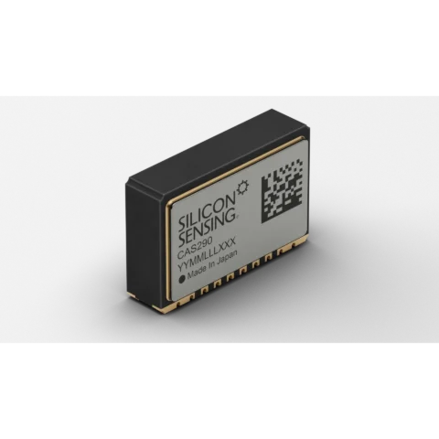
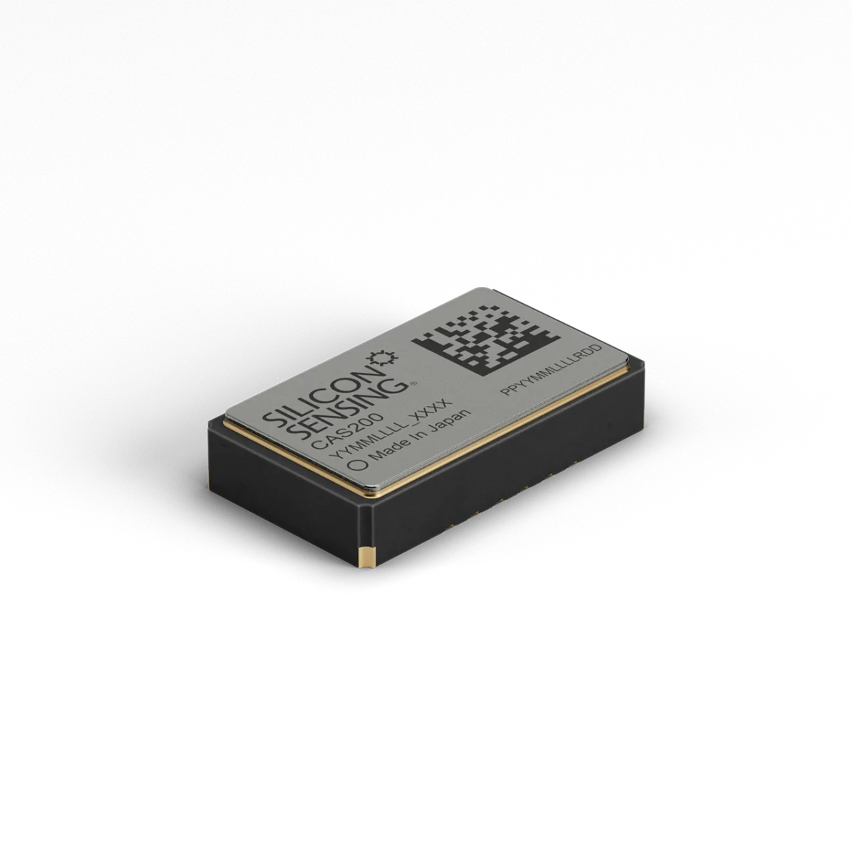
The CAS200 dual-axis MEMS accelerometer provides X- and Y-axis linear acceleration data from a compact, in-plane package. Each device combines a capacitive MEMS sensing element and dedicated control ASIC in a hermetically sealed ceramic LCC package measuring 10.4 × 6.0 × 2.2 mm. The series includes the CAS211, CAS212, CAS213, CAS214 and CAS215, with fixed measurement ranges from ±0.85g to ±96g. Acceleration and device-temperature data are available through analogue outputs or a digital SPI interface, while the digital interface also provides built-in-test status. A nominal 3.3 V supply, typical current consumption of 3 mA and direct surface-mount PCBA integration simplify board-level implementation.
Digital bandwidth above 170 Hz and analogue bandwidth above 250 Hz support control, navigation and motion-measurement systems. Typical applications include AHRS, platform stabilisation, drilling guidance, surveying, navigation, transport monitoring, IMUs, levelling and tilt sensing. The -40°C to +125°C operating range and 1,000g operational shock rating suit demanding industrial and aerospace environments when the range, mounting and signal conditioning are matched to the application.
Range features
A high level overview of what this range offers
- Two in-plane sensing axes: Measures X- and Y-axis linear acceleration from one board-mounted device.
- Five fixed acceleration ranges: Matches the measuring span to low-g or high-dynamic applications with ±0.85g, ±2.5g, ±10g, ±30g and ±96g variants.
- Analogue and digital outputs: Supports direct analogue acquisition or connection to a host through a 4-wire SPI interface.
- Integrated temperature measurement: Supplies analogue and digital temperature data for monitoring and compensation routines.
- Digital built-in-test status: Supports start-up checks and sensor-health monitoring through the SPI interface.
- Hermetically sealed ceramic LCC package: Provides a compact surface-mount format with resistance to temperature and humidity exposure.
- Digital bandwidth above 170 Hz: Supports digital control, navigation and motion-measurement applications.
- Analogue bandwidth above 250 Hz: Provides a wider signal path for systems using analogue acquisition.
- 3 mA typical current consumption: Limits sensor power demand in board-level systems.
- 20 ms maximum start-up time: Makes acceleration data available shortly after power-up.
- -40°C to +125°C operation: Supports equipment exposed to wide ambient-temperature changes.
- 1,000g operational shock rating: Provides defined mechanical robustness for high-shock installations.
What’s in this range?
All the variants in the range and a comparison of what they offer
Specifications table
| Specification | Value |
|---|---|
Product type | Board-mount dual-axis linear accelerometer |
Sensor architecture | Capacitive MEMS sensing element with dedicated control ASIC |
Sense axes | 2, in-plane X and Y |
Variants | CAS211, CAS212, CAS213, CAS214 and CAS215 |
Measurement ranges | ±0.85g, ±2.5g, ±10g, ±30g or ±96g, depending on variant |
Package | Hermetically sealed, surface-mount ceramic LCC |
Dimensions | 10.4 × 6.0 × 2.2 mm |
Mass | 0.4 g typical |
Outputs | Analogue X/Y acceleration and temperature; SPI acceleration, temperature and status data |
Functional supply voltage | 2.7 to 3.6 V |
Full-specification supply range | 3.15 to 3.45 V across -40°C to +125°C |
Nominal supply voltage | 3.3 V |
Supply current | 3 mA typical; 5 mA maximum |
Digital bandwidth | Above 170 Hz |
Analogue bandwidth | Above 250 Hz |
Operating temperature | -40°C to +125°C |
Storage temperature | -55°C to +150°C |
Humidity limit | 90% RH maximum, non-condensing |
Start-up time | 20 ms maximum |
Recovery from over-range or shock | 10 ms maximum |
SPI interface | 4-wire slave interface, Mode 0, 48-bit messages |
SPI message rate | 1 Hz to 10 kHz; 1 kHz recommended |
SPI clock | 100 kHz to 8 MHz; 1 MHz nominal |
Recommended minimum sampling rate | Above 500 Hz to reduce aliasing |
Digital temperature scale factor | 11 LSB/°C typical, with 2,380 LSB offset at +25°C |
Analogue temperature scale factor | 5 mV/°C typical, with 1.49 V offset at +25°C |
Temperature repeatability | -5°C to +5°C |
Sensor misalignment | -20 to +20 mrad |
Inter-axis orthogonality | 1.7 mrad typical |
Operational shock | 1,000g, 1 ms half-sine |
Non-operational shock | 6,500g, 0.1 ms half-sine for CAS211–CAS213; 10,000g, 0.1 ms half-sine for CAS214–CAS215 |
ESD protection | 2 kV HBM |
Minimum unpowered life | 15 years |
Minimum powered life | 12,000 hours |
Compliance | RoHS compliant |
Variant comparison
| Specification | CAS211 | CAS212 | CAS213 | CAS214 | CAS215 |
|---|---|---|---|---|---|
Sense axes | 2 | 2 | 2 | 2 | 2 |
Nominal supply | 3.3 V | 3.3 V | 3.3 V | 3.3 V | 3.3 V |
Acceleration range | ±0.85g | ±2.5g | ±10g | ±30g | ±96g |
Digital scale factor | 33,500 LSB/g | 11,000 LSB/g | 2,800 LSB/g | 1,050 LSB/g | 300 LSB/g |
Analogue scale factor | 1,150 mV/g | 375 mV/g | 96 mV/g | 36 mV/g | 10 mV/g |
Digital scale-factor error at +25°C | ±1% | ±1% | ±1% | ±1% | ±1% |
Analogue scale-factor error at +25°C | ±1.5% | ±1.5% | ±1.5% | ±1.5% | ±1.5% |
Scale-factor variation over temperature | ±1.2% | ±1.2% | ±1.2% | ±1.2% | ±1.2% |
Scale-factor non-linearity | 0.5% FSR | 0.5% FSR | 2% FSR | 2% FSR | 2% FSR |
Bias repeatability at +25°C | ±0.35 mg | ±0.75 mg | ±0.75 mg | ±3.0 mg | ±8.0 mg |
Bias stability over one year | ±7.5 mg | ±7.5 mg | ±7.5 mg | ±25 mg | ±75 mg |
Bias variation over temperature | ±50 mg | ±50 mg | ±50 mg | ±150 mg | ±500 mg |
Resolution or threshold at 1 Hz | 0.03 mg | 0.10 mg | 0.10 mg | 0.30 mg | 1.0 mg |
Noise spectral density | ≤50 µg/√Hz | ≤150 µg/√Hz | ≤150 µg/√Hz | ≤350 µg/√Hz | ≤1,200 µg/√Hz |
Nominal bandwidth |
|
|
|
|
|
Vibration rectification | 0.15 mg/g² at 0.5g RMS | 0.15 mg/g² at 2.0g RMS | 0.15 mg/g² at 8.0g RMS | 0.1 mg/g² at 12g RMS | 0.1 mg/g² at 12g RMS |
Typical current consumption | 3 mA | 3 mA | 3 mA | 3 mA | 3 mA |
Operating temperature | -40°C to +125°C | -40°C to +125°C | -40°C to +125°C | -40°C to +125°C | -40°C to +125°C |
Operational shock | 1,000g, 1 ms half-sine | 1,000g, 1 ms half-sine | 1,000g, 1 ms half-sine | 1,000g, 1 ms half-sine | 1,000g, 1 ms half-sine |
Velocity random walk | 0.07 m/s/√h | 0.07 m/s/√h | 0.07 m/s/√h | 0.07 m/s/√h | 0.07 m/s/√h |
FAQs
for CAS200 series (Dual-axis, in-plane) high-performance dual-axis linear accelerometer
Choose the lowest range that still covers the maximum expected acceleration, transient load and engineering margin without clipping. The CAS211 provides ±0.85g with a digital scale factor of 33,500 LSB/g and noise of up to 50 µg/√Hz, making it suitable for small motions, tilt and low-g measurement, while the CAS212 and CAS213 extend the range to ±2.5g and ±10g. The CAS214 and CAS215 cover ±30g and ±96g, but their digital scale factors fall to 1,050 and 300 LSB/g and their noise levels increase. The 1,000g operational shock rating is a survival specification and does not increase the measurable acceleration range or provide measurement headroom. Select the variant based first on measurable dynamics and overload margin, and then compare its noise, resolution and scale factor with the application requirements.
Use SPI when the host processor needs direct digital acceleration, temperature and status data, or when eliminating an external ADC simplifies the design. The interface is a 4-wire SPI Mode 0 slave using 48-bit messages, with a recommended message rate of 1 kHz, an allowed range from 1 Hz to 10 kHz and a nominal 1 MHz clock within a 100 kHz to 8 MHz range. Sampling above 500 Hz is recommended to reduce aliasing, although the digital sensor bandwidth remains above 170 Hz. Choose the analogue outputs when the design benefits from bandwidth above 250 Hz or already includes a suitable acquisition chain; because the outputs are ratiometric, ADC-reference and supply behaviour must be considered together. Interface selection should account for filtering, synchronisation and built-in-test handling rather than bandwidth alone.
The sensor operates functionally from 2.7 to 3.6 V, but all specified performance limits assume a tighter 3.15 to 3.45 V supply across the full -40°C to +125°C operating range. Current consumption is typically 3 mA, with a specified maximum of 5 mA. Fit a 100 nF X7R ceramic decoupling capacitor at the main supply, add a nearby 10 µF bulk capacitor and use separate 100 nF X7R capacitors for the Vdd_Cap and Vref_Cap connections. Avoid routing signal or power tracks beneath the capacitive sensor package where possible because they can introduce acceleration-bias offsets. These provisions reduce supply coupling and limit the compensation required during completed-system calibration.
The CAS200 operates from -40°C to +125°C and has a storage range of -55°C to +150°C, allowing it to be designed into equipment exposed to broad thermal cycles. Its hermetically sealed ceramic package provides resistance to humidity, while the stated absolute limit is 90% RH under non-condensing conditions. The operational shock rating is 1,000g for a 1 ms half-sine pulse. Non-operational survival is 6,500g for the CAS211 through CAS213 and 10,000g for the CAS214 and CAS215, using a 0.1 ms half-sine pulse. These values are survival limits rather than measurable ranges, and the PCB, solder joints and surrounding assembly still require application-level shock and vibration qualification.
The digital and analogue signal paths provide bandwidths above 170 Hz and 250 Hz respectively, but usable resolution depends strongly on the selected variant and the bandwidth retained after filtering. As a first-order white-noise estimate, RMS noise is calculated by multiplying noise spectral density by the square root of measurement bandwidth. Across a 100 Hz bandwidth, the CAS211 noise value of 50 µg/√Hz corresponds to approximately 0.5 mg RMS, while the CAS215 value of 1,200 µg/√Hz corresponds to approximately 12 mg RMS. Narrower filtering can reduce integrated noise when the application does not require the full response bandwidth. Engineers should therefore select the acceleration range and signal bandwidth together rather than treating them as independent requirements.
Yes, the integrated temperature channel can support host-level thermal compensation and operating-condition monitoring. The digital output has a typical scale factor of 11 LSB/°C with an offset of 2,380 LSB at +25°C, while the analogue output provides 5 mV/°C with an offset of approximately 1.49 V at +25°C. The stated temperature repeatability is within ±5°C, so the channel should not replace a calibrated external sensor where precise ambient-temperature measurement is required. It is most useful for correlating acceleration bias and scale-factor behaviour with the sensor’s own thermal state. Establish compensation curves on the completed assembly because PCB layout, mounting stress and local heating can affect the final system response.
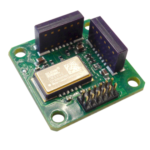
The matching CAS21x evaluation board can confirm the selected measurement range and interface before the host PCB design is finalised. The board measures 34 × 26 mm, operates from 3.3 V and provides access to both analogue outputs and the SPI bus for CAS21x variants spanning ±0.85g to ±96g. It supports early checks of scaling, bandwidth, noise, message handling and temperature data using the intended device. The board is intended for evaluation rather than integration as a permanent subsystem, so its mechanical, EMC and environmental behaviour should not be transferred directly to the final assembly. A production design still requires the recommended decoupling, controlled PCB layout, validated mounting process and system-level calibration.