TBF500 Series AC/DC Power Supplies
- Technology
- PCB AC-DC power supplies
- Partner
- P-DUKE
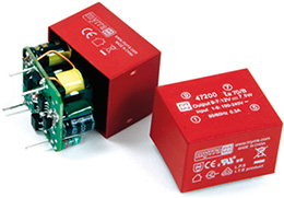
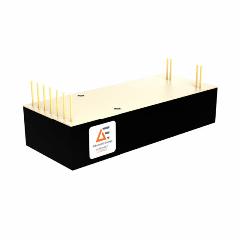
The TBF500 Series is a family of board-mounted AC/DC power supplies delivering up to 500W with conduction cooling. Its universal 85–264VAC input range allows the same module family to operate from common international mains supplies, while an 88–370VDC input range is also supported. Designers can select 12V, 15V, 24V, 28V, 48V or 54V single-output models, with rated currents from 9.4A to 42A. The encapsulated full-brick construction uses an aluminium baseplate to transfer heat into a chassis or optional heatsink. Remote sensing, output trimming, remote on/off control and a power-good signal simplify integration into monitored power architectures. Models with the -S suffix add active droop current sharing for parallel systems using up to three modules. Typical applications include railway electronics, factory automation, telecommunications, robotics, energy storage, measurement equipment and defence systems.
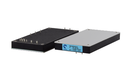
The TBF500 Series is designed for high-density board-level AC/DC conversion where a compact full-brick format, conduction cooling and broad application coverage are required. It accepts 85–264VAC mains input and also supports 88–370VDC, allowing use across international AC systems and compatible high-voltage DC buses.
Available single-output variants cover 12V, 15V, 24V, 28V, 48V and 54V, with rated output currents from 42A down to 9.4A depending on model. Integrated functions such as remote sense, output trim, remote on/off and power-good signalling help the series fit monitored and controlled power architectures. For higher-power parallel systems, -S models provide active droop current sharing for up to three modules when the recommended installation rules are followed.
Range features
A high level overview of what this range offers
- 500W conduction-cooled output: Delivers substantial board-level power from a low-profile full-brick module.
- 85–264VAC universal input: Supports equipment intended for different regional mains supplies.
- 88–370VDC input capability: Enables use on compatible high-voltage DC distribution systems.
- Six output-voltage options: Covers 12V, 15V, 24V, 28V, 48V and 54V rails within one series.
- Up to 93% efficiency: Reduces heat that must be removed through the baseplate.
- Encapsulated construction: Suits demanding industrial and transportation environments.
- 12.7mm module height: Helps in installations with limited vertical clearance.
- Remote sensing and output trim: Compensates wiring losses and allows controlled voltage adjustment.
- Remote on/off and power-good functions: Supports sequencing, supervision and controlled system behaviour.
- Optional active droop current sharing: Allows up to three
-Smodules to operate in parallel. - Integrated fault protection: Includes overload, short circuit, output overvoltage and overtemperature protection.
- OVC III insulation design: Supports use in overvoltage category III environments.
- Operation up to 5,000m: Accommodates elevated-altitude installations within the stated limits.
- Railway-related standards: Includes EN 50155 and EN 45545-2 among the listed standards.
What’s in this range?
All the variants in the range and a comparison of what they offer
| Model | Power (W) | Vin (V) | Vout (VDC) | Isolation | Status |
|---|---|---|---|---|---|
TBF500US24 | 500 | 85 ~ 264 | 24 | 3000 VAC | Active |
TBF500US54 | 500 | 85 ~ 264 | 54 | 3000 VAC | Active |
TBF500US15 | 500 | 85 ~ 264 | 15 | 3000 VAC | Active |
TBF500US48 | 500 | 85 ~ 264 | 48 | 3000 VAC | Active |
TBF500US12 | 500 | 85 ~ 264 | 12 | 3000 VAC | Active |
TBF500US28 | 500 | 85 ~ 264 | 28 | 3000 VAC | Active |
FAQs
for TBF500 Series AC/DC Power Supplies
Select the model by matching its nominal voltage, continuous current and allowable capacitive load to the downstream system. The 12V model supplies 42A, while the 15V, 24V, 28V, 48V and 54V versions provide 33.5A, 21A, 18A, 10.5A and 9.4A respectively. Maximum capacitive load decreases from 20,000µF on the 12V model to 820µF on the 54V model. The load must also remain within the thermal derating limits rather than being assessed from current alone. Engineers should review start-up demand, cable losses and transient loads before fixing the required voltage variant.
The 500W rating is specified for conduction-cooled operation at 230VAC, so the aluminium baseplate must have an effective thermal path into the chassis or a suitable heatsink. The permitted baseplate temperature range is −40°C to +105°C with derating, and the characteristic curve shows that available power reduces near the upper temperature limit. Input-voltage derating also applies near the bottom of the 85–264VAC range. The module’s encapsulation does not remove the need to verify thermal performance under the actual airflow, mounting and ambient conditions. Baseplate temperature should therefore be measured at the designated test point during qualification.
An external fuse, bulk capacitance and thermal fuse resistor are required because these elements are not all integrated within the module. Input protection calls for a T10A/250VAC slow-blow fuse, while the bus capacitor arrangement uses a minimum 450VDC rating and an allowable total capacitance of 660–2,200µF. A resistor must be connected between the inrush-control and positive bus pins; without it, correct operation is not assured. A 4.7–22Ω, 5–10W overtemperature-protected resistor is recommended, with 12Ω, 130°C and 5W used in the typical circuit. The specified external EMC network must also be incorporated when the stated emissions performance is required.
Remote sensing should be connected at the load when distribution resistance would otherwise cause an unacceptable voltage drop. The sense conductors should be short, routed close together and implemented as a twisted or shielded pair when wires are used. If remote sensing is not required, each sense pin must be connected directly to the corresponding output terminal. Standard models permit adjustment from −10% to +10%, while current-share versions are limited to ±5%; the sense correction is included within these total limits. This means the trim setting and expected wiring loss must be considered together to prevent the output from exceeding its permitted adjustment range.
Yes, but active current sharing requires models carrying the -S suffix and no more than three modules may be paralleled. Each module should be operated at no more than 85% of its 500W rating, giving a practical design limit of 425W per unit and 1,275W for three modules. Output wiring from every module to the load should have closely matched resistance, and each unit requires its own bus capacitor and thermal fuse resistor. The specified droop rate is 4%, with 20% current-share accuracy at full load. Applying the main load after all modules have established their outputs helps prevent the first module to start from entering overload protection.
Overload protection operates in hiccup mode at approximately 145% of the maximum rated output current. A continuous short circuit also causes cycling with automatic recovery, allowing the module to restart after the fault is removed. Output overvoltage protection is different: it operates between 115% and 135% of nominal voltage and latches the module off. Overtemperature protection uses an internal thermistor with a 115°C threshold and hiccup behaviour. System control logic should account for these different recovery methods, particularly where a latched overvoltage event requires input power to be removed before normal operation can resume.
The listed standards include EN 50155, EN 45545-2 and the IEC/EN/UL 62368-1 safety framework, alongside EN 50121-3-2 and EN 50121-4 railway EMC requirements. Mechanical testing references EN 61373 for shock and vibration, as well as MIL-STD-810F environmental methods. Conducted Class B and radiated Class A emissions performance depends on installing the specified external filtering components and following the recommended layout. The baseplate can be connected to functional earth through the M3 mounting holes to assist EMI control. Final equipment still requires system-level testing because enclosure construction, grounding, cable routing and load behaviour can alter compliance results.