Vacuum Residual Gas Analysers
- Technology
- Scientific instruments
- Partner
- Stanford Research Systems (SRS)
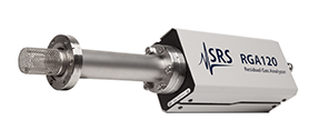
This product range covers the RGA100 and RGA120 residual gas analyser series and six mass-range variants. Each system combines an open ion source quadrupole probe, a detachable electronics control unit and Windows-based software for instrument control, acquisition and analysis. Better than 0.5 amu resolution at 10% peak height enables adjacent nominal masses to be resolved across the selected operating range. A Faraday cup is fitted as standard, while an optional continuous-dynode electron multiplier extends the minimum detectable partial pressure from 5 × 10⁻¹¹ Torr to 5 × 10⁻¹⁴ Torr.
Applications include residual gas composition analysis, contamination investigation, vacuum leak detection, system diagnosis and process monitoring. The RGA100 series provides RS-232C control, with Ethernet connectivity available through an external adapter. The RGA120 series adds automatic peak tuning, built-in process I/O and standard USB, Ethernet and RS-232C interfaces.
Range features
A high level overview of what this range offers
- Six mass-range variants – Match the analyser to gases and fragments between 1 and 320 amu.
- Quadrupole mass filter – Delivers better than 0.5 amu resolution at 10% peak height.
- Standard Faraday cup detector – Supports partial-pressure measurements down to 5 × 10⁻¹¹ Torr.
- Optional continuous-dynode electron multiplier – Extends detection to 5 × 10⁻¹⁴ Torr for lower-level species.
- Wide-range electrometer – Measures ion currents from 10⁻⁷ to 10⁻¹⁵ A within one scan.
- Open SS304 ion source – Supports gas sampling within high- and ultra-high-vacuum chambers.
- Dual thoriated-iridium filament – Field-replaceable construction supports planned maintenance.
- Built-in degassing and pressure protection – Helps reduce ion-source background and protect the filament during overpressure conditions.
- Detachable electronics control unit – Permits probe bakeout at temperatures up to 300 °C without the electronics attached.
- RGA120 process I/O – Analogue input and output, relay, GPIO, RTD and trigger connections support equipment integration.
- Programmable operation – Enables automated scanning, leak testing, instrument control and remote data collection.
- Windows acquisition software – Provides live spectra, scheduled logging, composition analysis, alarms, CSV export and multi-head operation.
Downloads
for Vacuum Residual Gas Analysers
What’s in this range?
All the variants in the range and a comparison of what they offer
Specifications Table
| Category | Specification | RGA100 Series | RGA120 Series |
|---|---|---|---|
Operational | Model mass ranges | RGA100: 1–100 amu | RGA120: 1–120 amu |
Operational | Mass filter | Quadrupole | Quadrupole |
Operational | Detector configuration | Faraday cup standard; continuous-dynode electron multiplier optional | Faraday cup standard; continuous-dynode electron multiplier optional |
Operational | Resolution | Better than 0.5 amu at 10% peak height to AVS Standard 2.3; adjustable to constant peak width | Better than 0.5 amu at 10% peak height to AVS Standard 2.3; adjustable to constant peak width |
Operational | Sensitivity | 2 × 10⁻⁴ A/Torr with Faraday cup; less than 200 A/Torr with electron multiplier | 2 × 10⁻⁴ A/Torr with Faraday cup; less than 200 A/Torr with electron multiplier |
Operational | Minimum detectable partial pressure | 5 × 10⁻¹¹ Torr with Faraday cup; 5 × 10⁻¹⁴ Torr with electron multiplier | 5 × 10⁻¹¹ Torr with Faraday cup; 5 × 10⁻¹⁴ Torr with electron multiplier |
Operational | Operating pressure | 10⁻⁴ Torr to UHV with Faraday cup; 10⁻⁶ Torr to UHV with electron multiplier | 10⁻⁴ Torr to UHV with Faraday cup; 10⁻⁶ Torr to UHV with electron multiplier |
Operational | Total-pressure measurement | Available through Faraday cup ion-current measurements | Available through Faraday cup ion-current measurements |
Operational | Electrometer | Temperature-compensated logarithmic design; 10⁻⁷ to 10⁻¹⁵ A in one scan; better than 2% precision | Temperature-compensated hybrid linear/logarithmic design; 10⁻⁷ to 10⁻¹⁵ A in one scan; better than 2% precision |
Operational | Scan capability | Selectable acquisition rates from 2000 to 15 ms/amu | Approximately 130.2 amu/s in histogram mode or 260.4 amu/s in analogue mode at 10 points per amu |
Environmental | Maximum operating temperature | 70 °C | 70 °C |
Environmental | Maximum probe bakeout temperature | 300 °C without the electronics control unit | 300 °C without the electronics control unit |
Environmental | Recommended bakeout temperature | 200 °C with the compatible heater jacket | 200 °C with the compatible heater jacket |
Ion source | Design and material | Open SS304 ion source with cylindrical symmetry and electron-impact ionisation | Open SS304 ion source with cylindrical symmetry and electron-impact ionisation |
Ion source | Filament | Dual thoriated-iridium; firmware protected and field replaceable | Dual thoriated-iridium; firmware protected and field replaceable |
Ion source | Degas control | Programmable 1–10 W ramp | Programmable 1–8 W ramp |
Ion source | Electron energy | 25–105 V, programmable | 25–110 V, programmable |
Ion source | Ion energy | 8 or 12 V | 4–16 V, programmable |
Ion source | Focus voltage | 0–150 V, programmable | 0–110 V, programmable |
Ion source | Electron emission current | 0–3.5 mA, programmable | 0–4 mA, programmable |
Process I/O | Analogue output | None | 0–20 V or 4–20 mA; selectable emission-current, temperature, pressure, ion-current and user-value functions |
Process I/O | Analogue input | None | 0–10 V, 4–20 mA or 4–20 mA with loop power |
Process I/O | Event relay | None | Configurable DPDT; maximum 60 W, 75 VA, 125 VDC, 150 VAC or 2 A |
Process I/O | GPIO | None | Configurable 0–3.3 V digital input or output |
Process I/O | Temperature input | None | Nominal Pt100 RTD input |
Process I/O | Trigger input | None | 0–3.3 V with programmable transition level |
Communications | Computer interfaces | RS-232C at 28,800 baud with RTS/CTS flow control; optional external 10/100 Ethernet adapter | USB 2.0 full speed, 10/100 Base-T Ethernet and RS-232C at 28,800 baud |
Communications | Ethernet protocols | TCP/IP network connection through the external adapter | TCP, UDP and DHCP |
Software | Acquisition and analysis | RGA Windows software with analogue, histogram, pressure-versus-time and leak-test modes | RGASoft software with analogue, histogram, pressure-versus-time and leak-test modes |
Mechanical | Probe length | 8.75 in from flange face to top of ioniser | 8.75 in from flange face to top of ioniser |
Mechanical | Probe insertion | 2.0 in | 2.0 in |
Mechanical | Mounting flange | 2.75 in CF | 2.75 in CF |
Mechanical | Minimum port internal diameter | 1.375 in | 1.375 in |
Mechanical | Electronics control unit dimensions | 9.1 × 4.1 × 3.1 in | 9.1 × 4.1 × 3.1 in |
General | Warm-up time | ±0.1 amu mass stability after 30 minutes | ±0.1 amu mass stability after 30 minutes |
General | DC power | 24 VDC at 2.5 A through a male DB9 connector | 24 VDC at 2.5 A through a 5.5 mm OD × 2 mm ID barrel connector |
General | Optional AC power module | 110, 120, 220 or 240 VAC at 50/60 Hz | 110, 120, 220 or 240 VAC at 50/60 Hz |
General | Weight | 6 lb | 6 lb |
General | Warranty | One year for defects in materials and workmanship | One year for defects in materials and workmanship |
Variant Comparison
| Specification | RGA100 | RGA200 | RGA300 | RGA120 | RGA220 | RGA320 |
|---|---|---|---|---|---|---|
Mass range | 1–100 amu | 1–200 amu | 1–300 amu | 1–120 amu | 1–220 amu | 1–320 amu |
Standard computer interface | RS-232C | RS-232C | RS-232C | USB, Ethernet and RS-232C | USB, Ethernet and RS-232C | USB, Ethernet and RS-232C |
Ethernet arrangement | External 10/100 adapter | External 10/100 adapter | External 10/100 adapter | Built-in 10/100 Base-T | Built-in 10/100 Base-T | Built-in 10/100 Base-T |
Built-in process I/O | No | No | No | Analogue I/O, relay, GPIO, Pt100 RTD and trigger | Analogue I/O, relay, GPIO, Pt100 RTD and trigger | Analogue I/O, relay, GPIO, Pt100 RTD and trigger |
Detector options | Faraday cup or optional electron multiplier | Faraday cup or optional electron multiplier | Faraday cup or optional electron multiplier | Faraday cup or optional electron multiplier | Faraday cup or optional electron multiplier | Faraday cup or optional electron multiplier |
FAQs
for Vacuum Residual Gas Analysers
Choose first by mass range, then by control and process-integration requirements. The RGA100 family covers 1–100, 1–200 or 1–300 amu and communicates through RS-232C, with Ethernet available through an external adapter. The RGA120 family covers 1–120, 1–220 or 1–320 amu and adds USB, built-in 10/100 Ethernet, analogue I/O, relay, GPIO, Pt100 RTD and trigger connections. It also supports automatic peak tuning and analogue scans up to 260.4 amu/s at 10 points per amu. For new automated equipment, the RGA120 provides the broader integration set, while the RGA100 remains suitable where its mass range and serial-control architecture match an existing design.
Specify the electron multiplier when target partial pressures fall below the practical range of the standard Faraday cup or when low-level measurements require shorter acquisition times. The Faraday cup has a minimum detectable partial pressure of 5 × 10⁻¹¹ Torr, while the multiplier extends this to 5 × 10⁻¹⁴ Torr under the stated nitrogen measurement conditions. The applicable chamber-pressure range also differs: the Faraday cup can operate from 10⁻⁴ Torr towards UHV, whereas multiplier operation begins at 10⁻⁶ Torr. Total-pressure measurement is associated with Faraday cup ion-current measurements. Designs using the multiplier should therefore include suitable pressure interlocking, gain calibration and a method of reverting to the Faraday cup when chamber pressure rises.
The probe mounts on a 2.75 in CF flange and requires a vacuum port with a minimum internal diameter of 1.375 in. Probe insertion is 2.0 in, the distance from the flange face to the top of the ioniser is 8.75 in, and approximately 2.5 in of chamber clearance is required around the exposed ioniser region. The electronics control unit measures 9.1 × 4.1 × 3.1 in and can be separated from the probe before bakeout. The probe can withstand up to 300 °C without the control unit, although 200 °C is the recommended bakeout temperature with the compatible heater jacket. Normal operation is limited to 70 °C, so installation planning should account for process heat, ventilation and service access.
The RGA120 series provides the connections needed for direct interaction with many process-control systems. Its analogue output can be configured for 0–20 V or 4–20 mA and linked to variables such as total pressure, mass ion current, temperature or emission current. The analogue input accepts 0–10 V, 4–20 mA or 4–20 mA with loop power, while the DPDT relay is rated up to 60 W, 75 VA, 125 VDC, 150 VAC or 2 A. A 0–3.3 V GPIO, trigger input and Pt100 RTD input are also included. The RGA100 series instead relies on RS-232C commands, with network control possible through the external Ethernet adapter, so additional control hardware may be required for direct PLC integration.
Quantitative work requires gas-specific sensitivity factors and suitable fragmentation data rather than relying only on a library spectrum. A pure calibration gas is normally introduced at a known pressure, typically around 10⁻⁶ Torr, and its principal mass peak is measured using the Faraday cup. The sensitivity factor is calculated from the change in ion-current peak height divided by the corresponding change in partial pressure. Electron energy, ion energy, emission current, peak width, detector type and other operating settings must remain consistent between calibration and subsequent measurements. If the electron multiplier is used, its gain should be treated as a separate correction factor so that changes in multiplier gain are not mistaken for changes in the intrinsic sensitivity of the analyser head.
The resolution specification means that peaks separated by one nominal atomic mass unit can normally be distinguished when the instrument is correctly tuned. It is defined at 10% of peak height in accordance with AVS Standard 2.3, and the peak width can be held constant across the selected mass range. This is appropriate for identifying many common vacuum species and their fragments, including hydrogen, water, nitrogen, oxygen, argon and carbon dioxide. It does not separate different species that produce ions at exactly the same mass-to-charge ratio, such as nitrogen and carbon monoxide at mass 28. Those cases must be resolved by examining additional fragment peaks, isotopic ratios, process history and calibrated fragmentation patterns.
Both series use a dual thoriated-iridium filament with firmware-based protection and field-replaceable construction. The RGA100 monitors for overpressure at 675 Hz during operation, while the RGA120 checks process pressure before enabling the filament and reports pressure-related errors through its status system. A programmable degas function applies a controlled power ramp of 1–10 W on the RGA100 series or 1–8 W on the RGA120 series to reduce contamination associated with the ion source. The electronics control unit should be removed before high-temperature probe bakeout or probe servicing. Maintenance must use clean vacuum procedures because fingerprints, dust, unsuitable tools or contaminated replacement parts can raise background signals and compromise subsequent gas analysis.
The supplied Windows applications support analogue spectra, histogram scans, pressure-versus-time monitoring, leak testing and scheduled acquisition. Results can be displayed using linear or logarithmic scales and pressure units including Torr, bar and pascal, while alarms and gas labels can be configured for monitored species. Data can be exported in CSV format, and plots can be saved in common image and document formats for analysis or reporting. Multiple analyser heads can run concurrently through separate software instances, subject to the host computer’s available resources. For automated systems, the RGA120 supports SCPI control through USB, Ethernet or RS-232C, while the RGA100 uses its serial high-level command set and can be networked through the external Ethernet adapter.